


A pilot flies the same site every month. Same drone, same Dronelink mission, same Emlid Ground Control Point (GCP) markers in the same hat-marked spots. Eleven flights produced clean deliverables. The twelfth came back a meter low — but only away from the GCPs. Walk a checkpoint near a control marker, elevation reads correctly. Walk fifty feet into the field, the surface drops a meter underfoot. Same hardware, same workflow, same site, different answer.
This is vertical bias — the failure GCPs were supposed to prevent, and the one GCPs alone cannot diagnose.
What Vertical Bias Actually Is
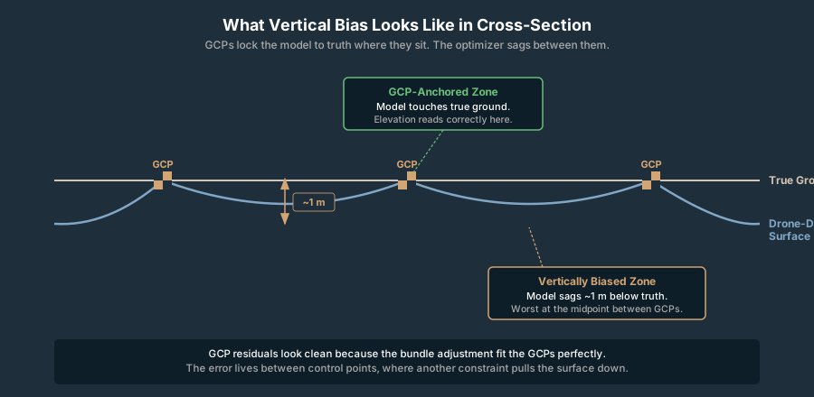
Vertical bias is a systematic offset in elevation across all or most of a photogrammetric model. Every elevation reads consistently high — or consistently low — by roughly the same amount. It is not random noise. It is not the curved arc of the doming effect. It is a flat directional shift, as if someone slid the entire surface down 0.8 meters and called it done.
In a quality report, vertical bias shows up as a non-zero mean of the Z residuals at your checkpoints. Random error has a mean near zero — positive and negative residuals cancel. A bias does not cancel. The whole population is shifted.
Read the mean Z residual paired with the standard deviation. Vertical Root Mean Square Error — vertical RMSE (RMSEV) — bundles both into one number. Convenient for RMSE reporting, useless for diagnosis. A 0.9 m mean with 0.05 m standard deviation is a different problem from a 0.0 m mean with 0.9 m standard deviation, and they require different fixes. Doming and vertical bias produce identical RMSEV numbers while needing opposite responses.
The trap with this failure mode — fine at the GCPs, off everywhere else — is that the GCP residuals look clean. Bundle adjustment fitted the GCPs perfectly because that is what bundle adjustment does. The error lives in the gaps between control points, where the optimizer compromised between the truth your GCPs encoded and a bad constraint from somewhere else in the dataset. Štroner and colleagues (2021, “Photogrammetry Using UAV-Mounted GNSS RTK: Georeferencing Strategies without GCPs,” Remote Sensing) showed systematic elevation deviations up to 30× the GSD on RTK-only flights, and demonstrated that focal-length drift and EXIF altitude bias can leave residual vertical error away from the control points even with GCPs in the bundle.
That is the gap this article fills. GCPs are necessary for accurate vertical, not sufficient. When they fail to save you, the question is not whether to add more — it is which constraint in the bundle adjustment is fighting them.
How to Read the Failure in the Quality Report
Before walking the diagnostic tree, pull the report and triage. Three numbers do most of the work.
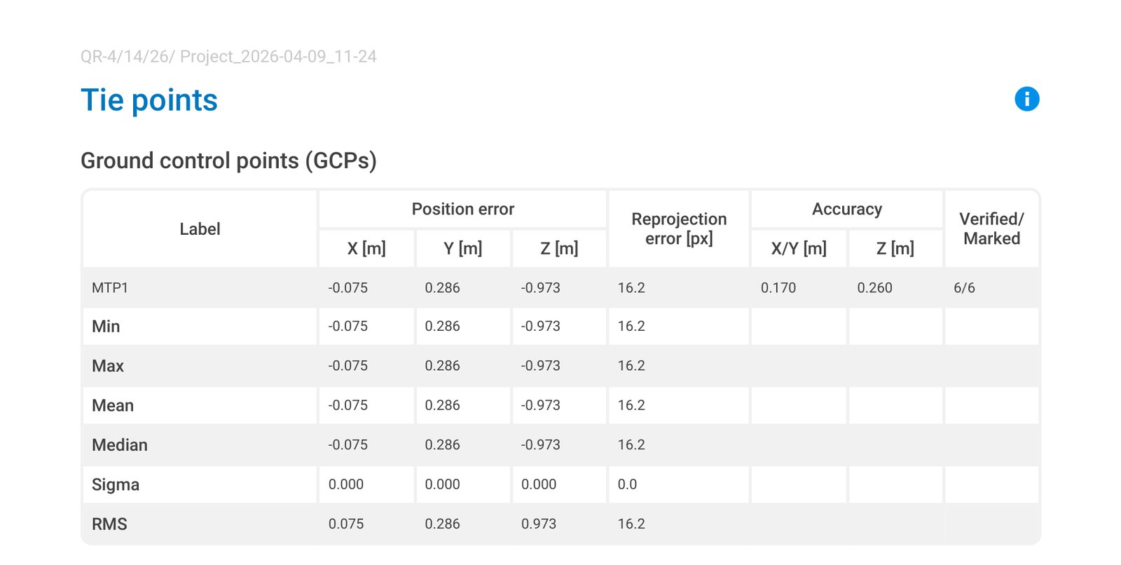
GCP Z residuals. These should be sub-centimeter. If they are not, your GCP coordinates do not match your image network — focus there before anything else.
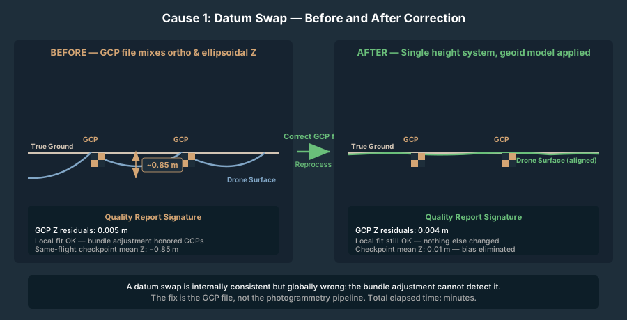
Checkpoint Z residuals. These are the real accuracy. If GCP Z is 0.005 m and checkpoint Z mean is 0.85 m, the model is locally correct and globally wrong. That is the signature pattern.
Camera Z bias. Most quality reports include an “estimated vs initial” comparison for the cameras. If your initial Exchangeable Image File Format (EXIF) altitudes were 122 m and the optimizer pushed them to 115 m, that 7-meter swing is the bundle adjustment fighting your GCP block.
Pix4D’s quality report frames the Z residual as original position − computed position, so a positive mean residual means the surveyed checkpoint sits above the model — the model is biased low. That sign convention varies between vendors; confirm yours before drawing conclusions. The drone mapping quality report breakdown walks through the per-image and per-GCP tables in more detail.
The Diagnostic Decision Tree
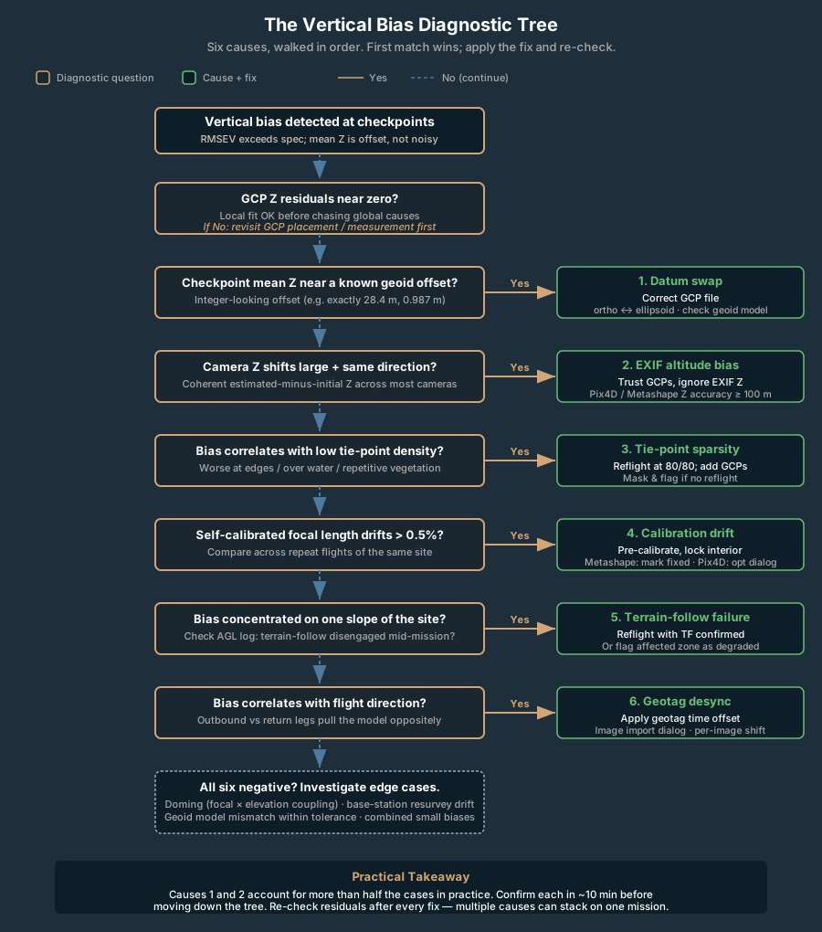
Six causes account for nearly every vertical-bias failure on a properly configured GCP-controlled mission. Walk them in order — the first two cause more than half the cases practitioners report, and they take ten minutes each to confirm.
1. Vertical Datum Swap in the GCP File
Failure signature. GCP Z residuals near zero. Checkpoint Z residuals clustered tightly with a near-constant mean offset between roughly 20 m and 30 m, or 0.5 m to 2 m. The model is internally consistent — it is just sitting at the wrong elevation.
Why this happens. Your GCPs were collected one month in NAVD88 orthometric heights. The next month they came back from the survey pipeline as ellipsoidal heights from the GNSS receiver, and your processing software assumed orthometric. Geoid separation in the continental US ranges from roughly −53 m to −8 m depending on location (NGS, GEOID18). A swap of 30 m is the most dramatic version. A subtler version — the one that produces the “1 meter low” report above — is when a single GCP file column was reformatted, mixing the two height types within the same file.
A second flavor: the Real-Time Kinematic (RTK) base was resurveyed between flights and the operator did not update the project. If the base station’s published height shifts, every GCP coordinated against that base shifts with it.
How to confirm. Open the GCP file. Compare one GCP’s Z value against the surveyed value in your project records. If they differ by an integer-looking number — exactly 28.4 m, or exactly 0.987 m — you have a datum problem. Check the receiver’s height output mode (orthometric vs ellipsoidal), the geoid model selected in post-processing, and the project CRS definition in your photogrammetry software’s vertical component. The coordinate systems primer walks through the geoid-vs-ellipsoid distinction in field-usable terms.
Fix. Correct the GCP file. Reprocess. Done.
2. EXIF GPS Altitude Bias on a Non-RTK Drone
Failure signature. GCP Z residuals near zero. Checkpoint Z residuals trending in the same direction as the EXIF-to-solution camera Z shift. Camera Z shifts visible in the report — often 5 m to 50 m. Effect strongest in the middle of the block, weaker near GCPs.
Why this happens. Consumer and pro-sumer drones use barometric altimeters cross-referenced against single-frequency GPS. Barometric readings drift with atmospheric pressure through the flight. Barometer-based altitude is typically accurate to within roughly 10 feet (3 m), but drift accumulates on longer missions — operator field reports document drift exceeding 10 m on hour-long flights. The bundle adjuster reads the EXIF GPS altitude on every image and uses it as a soft constraint on camera Z. If those altitudes are biased low by 30 m, the optimizer compromises: pulls the cameras up toward the GCP-implied truth, pulls the surface down toward the EXIF-implied truth. Result: fine at the GCPs, biased low between them.
Štroner et al. (2021) demonstrated this directly in their RTK-only tests: vertical bias correlates strongly with focal-length and camera-Z misestimation, and the failure persists at distance from the GCPs even when GCP-block residuals look clean.
How to confirm. In the quality report, look at the camera position adjustments. If estimated minus initial Z is a coherent shift in one direction across most or all cameras (not random scatter), EXIF is fighting the GCPs. The magnitude of the camera shift will roughly match the magnitude of the surface bias.
Fix. Three options, in order of effort. (1) In Pix4D, set image geolocation accuracy to a very large number for Z, or disable the EXIF altitude entirely — this tells the optimizer to trust GCPs and ignore EXIF altitude. In Metashape, set camera location accuracy in Z to 100 m or more. In OpenDroneMap (ODM), raise --gps-accuracy to a large value (e.g., 100) so the optimizer weights GCPs over EXIF, or use --gps-z-offset to apply a known altitude correction; avoid --force-gps unless your EXIF positions are reliable. (2) Reflight with RTK if available. (3) Pre-correct the EXIF altitudes against a known reference before processing.
3. Sparse Tie-Point Coverage Away From GCPs
Failure signature. GCP Z clean, checkpoint Z residuals worsen with distance from the nearest GCP, model edges and corners noticeably worse than center. Tie-point density map from the report shows thin coverage in the affected zone.
Why this happens. Bundle adjustment propagates GCP control through the tie-point network. If a region has few or low-quality tie points — repetitive vegetation, water, snow, deep shadow, a freshly graded dirt pad — the optimizer cannot transfer the GCP constraint into that zone. The surface there is anchored only by the EXIF camera positions and the tie-point geometry, both of which carry vertical error.
The doming effect article covers the related geometric failure where the entire surface bows due to focal-length-vs-elevation correlation. Sparse-tie-point bias is the simpler cousin: not a global bow, just a regional miss.
How to confirm. Pull the dense tie-point map from the report. Overlay your checkpoint locations. Bias zones tend to land in low-tie-point regions. Cross-reference with the orthomosaic — repetitive textures and water are the usual culprits.
Fix. Increase overlap on the next flight; target 80/80 minimum on featureless terrain. Add GCPs in the low-tie-point zones if reflyable. For an existing dataset with no extra control, mask the low-tie-point regions in the deliverable and flag them as estimated rather than measured.
4. Camera Self-Calibration Drift Between Flights
Failure signature. GCP Z clean, checkpoint Z biased, the bias amount varies between repeat flights of the same site even when the workflow is unchanged. Estimated focal length differs flight-to-flight by more than 0.5 percent.
Why this happens. When a photogrammetry pipeline runs self-calibration, it estimates focal length, principal point, and distortion coefficients per dataset. Focal length and camera Z are mathematically correlated during the bundle adjustment — a small focal-length error propagates directly into vertical bias because the optimizer can trade one for the other. Temperature, mechanical shock, and a recently swapped lens can all shift the actual interior orientation between flights. Thermal focal-length drift in image-sensor cameras is well-documented during ambient temperature swings — non-trivial for sub-meter vertical work.
How to confirm. Compare the estimated focal length, principal point, and radial distortion coefficients across recent flights of the same hardware. A self-calibration that is reasonably stable (focal length within 0.1 percent) across flights points elsewhere; a self-calibration that drifts is your problem.
Fix. Pre-calibrate the camera against a calibration target and lock the interior orientation in the photogrammetry software (in Metashape, mark the calibration parameters as fixed; in Pix4D, use the camera optimization parameters dialog). Reprocess with the locked calibration. The trade-off: a fixed calibration that no longer matches the actual lens (e.g., after temperature swings or a hard landing) introduces its own bias. Mid-mission temperature monitoring or pre-flight calibration shots help bound the risk.
5. Terrain-Follow Failure Mid-Mission
Failure signature. Vertical bias concentrated on one slope of the project, often the steepest. Checkpoint Z residuals correlate spatially with elevation change. GCP locations on the well-mapped slopes look fine; the off-slope half is biased.
Why this happens. Terrain-follow modes plan the mission against a Digital Elevation Model (DEM) — typically SRTM or ASTER — and command the drone to follow the surface at constant Above Ground Level (AGL). If terrain-follow disengages mid-flight (DEM coverage gap, signal loss, manual override, drone reverting to Mean Sea Level (MSL) after a battery swap), the second half of the flight runs at constant MSL, varying Ground Sample Distance (GSD) and overlap with topography. The result is uneven tie-point density, uneven GCP-network coverage on slopes, and a model that fits cleanly where the flight executed correctly and biases where it did not. Check your flight app’s log for the terrain-follow engagement state (DJI Pilot 2 and Dronelink both expose this) to confirm it stayed active for the whole mission.
How to confirm. Pull the actual flight log. Plot drone AGL across the mission. Constant AGL through the whole flight means terrain follow worked. AGL diverging from terrain mid-flight means it didn’t. The bias zone matches the flight half where AGL drifted.
Fix. Reflight the affected zone with terrain follow confirmed engaged. If reflight is not an option, treat the affected zone as a known-degraded deliverable.
6. Image Timestamp / GPS Desync (Geotag Offset)
Failure signature. Bias correlated with flight direction. Cameras on the outbound leg pull the model one way; cameras on the return leg pull the other. RMSEV dominated by direction-dependent residuals.
Why this happens. The drone’s GPS receiver and camera shutter operate on different clocks. If they are out of sync by 0.5 seconds at 10 m/s ground speed, every image is geotagged 5 m from where it actually fired. The bundle adjuster gets a geotag track shifted along the flight direction — and altitude shifts with it because flight paths are rarely perfectly level over hilly terrain. Desync bias is usually horizontal, but on terrain with vertical change it bleeds into Z.
How to confirm. Compare the geotag track against the actual flight path log. A persistent forward or backward offset means desync. Many DJI drones apply a small built-in geotag time correction; check the manufacturer’s release notes or test against a ground reference for your specific model.
Fix. Apply a per-image geotag offset in the photogrammetry software. Pix4D and Metashape both support time-shift corrections in the image import dialog.
Diagnostic Decision Tree at a Glance
| Cause | Quick Confirm | Typical Fix |
|---|---|---|
| Vertical datum swap | GCP Z value ≠ surveyed Z by integer-looking offset | Correct GCP file, reprocess |
| EXIF altitude bias | Coherent camera Z shift in report | Disable EXIF altitude weight, or reflight with RTK |
| Tie-point sparsity | Low-tie-point regions overlap bias zones | More overlap, more GCPs in gaps |
| Calibration drift | Focal length differs between flights | Lock pre-calibrated camera parameters |
| Terrain-follow failure | Drone AGL drifts mid-flight in log | Reflight with terrain follow confirmed |
| Geotag desync | Bias correlates with flight direction | Apply time-shift correction in import |
What To Do TONIGHT If This Is Happening
When the deliverable is due tomorrow and the model is a meter low, walk this fast checklist before opening any new processing run.
- Pull the quality report. Read GCP Z residuals, checkpoint Z residuals, camera position shifts. Two minutes.
- Compare the GCP file Z values against your survey field book. Datum swaps are visible at this layer. Five minutes.
- Check the camera Z shift in the report. A coherent direction of EXIF-vs-solution shift larger than 5 m is your suspect. Two minutes.
- Pull the flight log and confirm constant AGL through the mission. Terrain-follow drops show up here. Three minutes.
- Check focal length against the previous flight’s report. Drift over 0.5 percent is meaningful. Two minutes.
- Run a checkpoint elevation extraction at five spots: one near each GCP corner and one at the center. A clean GCP-vicinity number with a biased center number confirms the trigger pattern.
Fifteen minutes total. If none of those steps surfaces a cause, you are in the long tail — geotag desync, atmospheric refraction, or a multi-cause combination. Reprocess with EXIF altitude weighting reduced to break the most common silent failure first, then triage from there.
When To Stop Trusting GCPs and Reflight
Three conditions trigger a reflight rather than a reprocess.
Tie-point coverage is below 50 images per ground point in the bias zone. No amount of GCP work will fix a model that did not have the imagery to support it. More overlap on the next flight is the only path forward.
Focal length is drifting flight-to-flight by more than 1 percent. The camera has a mechanical or thermal stability problem. Pre-calibration, lens replacement, or a different drone for vertical-critical work is the right call.
Terrain-follow disengagements are happening repeatedly on the same site. The DEM your planner is using does not match the ground. Custom DEM import or physical site survey to seed the planner solves it.
Checkpoint validation is the truth-teller in all six failure modes. Without independent checkpoints, none of these biases are visible until a third party walks the site with an RTK rover. The American Society for Photogrammetry and Remote Sensing (ASPRS) positional accuracy standard (Edition 2, Version 2, 2024) sets the formal minimum at 30 independent checkpoints for a statistically valid accuracy assessment, with a small-project pragmatic floor of 3–5 checkpoints when the count is explicitly disclosed in the accuracy statement. For a quick diagnostic, six well-placed checkpoints at center, edges, and corners catch every failure mode in this article.
GCPs are necessary for vertical accuracy. They are not sufficient. When the model is biased everywhere except around the control markers, the GCPs are doing their job — and the bundle adjustment is fighting another constraint that is just as influential and twice as easy to overlook.
The two highest-yield checks: vertical datum on the GCP file, and EXIF altitude bias in the camera positions. Those account for the majority of the failure pattern above, and both are confirmable in under ten minutes from the quality report and the GCP source file. Walk the rest of the tree only after those are clean.
A model that fits the GCPs perfectly is not the same as a model that fits reality. The checkpoints tell you which.