


A surveyor calls about a 60-acre topographic deliverable his client flagged for accuracy. He flew with a brand-new Matrice 4E, full Real-Time Kinematic (RTK) fix the entire flight, NTRIP corrections from the state CORS network. Horizontal numbers were beautiful — 3 cm horizontal Root Mean Square Error (RMSEH) on the four checkpoints he held back. Vertical RMSE (RMSEV) was 14 cm. The client’s spec was 5 cm vertical.
He did not place a single Ground Control Point (GCP). The RTK was working. The drone reported “FIX” for the entire mission. The base station was 8 km away on a known monument. By every indicator the platform gave him, the data should have been survey grade.
This is the most expensive misunderstanding in commercial drone mapping. RTK gets sold as a replacement for ground control, and for some purposes it is — but not for the purposes that actually pay. The reason is not bad gear or bad operators. It is a mismatch between what an RTK GNSS receiver measures and what a photogrammetric product needs to be accurate.
Here is what RTK actually does, why the vertical accuracy gap persists, which failure modes RTK cannot fix, and the specific cases where you can skip GCPs without losing your shirt.
What RTK Actually Measures
RTK is a GNSS technique where a fixed base station broadcasts correction data to a mobile rover — in this case the drone. The rover combines its own raw satellite observations with the base’s corrections and resolves the carrier-phase ambiguities to centimeter accuracy. When the math works, you get a “FIX” status and the rover reports its position with 1–3 cm precision in latitude, longitude, and ellipsoidal height.
That is the receiver position. Not the camera position. Not the photogrammetric product.
The receiver lives on the drone — typically on top, near the GPS antenna. The camera sits elsewhere — typically on a gimbal underneath. The vector between the GNSS antenna phase center and the camera optical center is the “lever arm.” On enterprise platforms it is on the order of 10–15 cm depending on body geometry — DJI does not publish exact lever-arm dimensions, so figures should be treated as estimates from the physical layout. The flight controller corrects for the lever arm with a fixed offset that does not account for gimbal articulation, vibration, or thermal drift in the mount.
Then there is timing. The RTK position is reported at the GNSS time epoch — typically once or twice per second. The camera fires at a different moment. The flight controller interpolates the position to the camera trigger timestamp. If trigger latency is off by 20 milliseconds and the drone is moving at 8 m/s, that is a 16 cm horizontal error that has nothing to do with the GNSS receiver.
Finally there is the geoid. The receiver reports ellipsoidal height — height above a mathematical ellipsoid. Surveyors and engineers need orthometric height — height above a geoid model that approximates mean sea level. Converting between them requires a geoid model (GEOID18 in the US, CGG2013a in Canada, etc.), and the conversion itself carries 1–3 cm of uncertainty depending on region and model version (NGS reports a nationwide 1σ of about 1.3 cm for GEOID18).
Add lever-arm uncertainty, timing latency, geoid model error, and residual GNSS noise, and the camera position at exposure time is accurate to 3–8 cm horizontal and 5–15 cm vertical — even when the receiver itself is accurate to 2 cm.
The Vertical Accuracy Gap
Run a controlled experiment. Fly the same 40-acre site twice, once a week, with the same drone and the same base station. Place 12 well-surveyed checkpoints on durable concrete pads. Process both flights through Metashape with no GCPs — RTK only — and compare the checkpoint residuals.
What you will find, consistently across DJI Matrice 4E, Mavic 3E, Skydio X10, and most other RTK platforms:
- RMSEH: 2–5 cm. Stable flight to flight. Often better than the spec sheet implies.
- RMSEV: 5–15 cm. Variable flight to flight. Often biased — the mean error is non-zero, with all checkpoints high or all checkpoints low rather than scattered around the truth.
Horizontal numbers reflect the fact that horizontal GNSS positioning is well constrained by satellite geometry — satellites are visible across the entire sky, so triangulation is strong in X and Y. Vertical positioning is weaker because satellites are only visible above the horizon, never below it. Geometric dilution of precision is roughly 2× worse vertically than horizontally.
Vertical bias — not noise, but offset — is the bigger problem. When all twelve checkpoints come in 8 cm high, that is not random error. That is a systematic shift in the model that no amount of additional checkpoints will diagnose. The shift comes from some combination of lever-arm error, geoid model mismatch, base-coordinate error in the vertical, and bundle-adjustment doming.
You cannot fix a systematic bias with statistics. You fix it with a ground tie.
Doming and Bowling
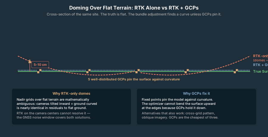
The second class of failure is geometric, not GNSS. The bundle adjustment — the optimization step where photogrammetry software solves for camera positions and 3D points simultaneously — has a well-known tendency to produce curved surfaces from flat ones. The terminology varies: doming, bowling, smile/frown. The mechanism is the same.
When a drone flies a nadir grid over flat terrain, the photogrammetric algorithm has an ambiguity. It can fit the data with the cameras at altitude A and the ground flat. Or with the cameras slightly lower, tilted inward at the edges, and the ground curved upward at the edges. Or curved downward. Mathematically, all three are nearly equivalent — the residuals fall within noise.
The bundle adjustment picks one. Which one depends on initialization, lens distortion residuals, the strength of the geometric constraints, and the specific algorithm. The result is a surface that may rise 10–30 cm above truth at the edges of the flight area, or sag below truth, with smooth curvature across the project.
GCPs fix this. Five or more well-distributed GCPs constrain the surface against curvature — the optimizer cannot bend the model upward at the edges because fixed points pin it down. Without GCPs, the model is free to bend.
RTK does not fix this. The RTK positions on the camera centers are themselves consistent with the doming solution. The optimizer can tilt the cameras slightly and curve the ground simultaneously within the noise of the GNSS measurements. In commonly reported field workflows, a “doming-corrected” RTK model can still dome by 5–10 cm — well within the GNSS noise window the bundle adjuster was working against (see James & Robson 2014 for the canonical treatment of the focal-length × elevation coupling that drives this).
The only fixes that work: GCPs, cross-grid flight patterns (which add geometric constraints), or oblique imagery alongside the nadir set. Of those three, GCPs are the most reliable, the cheapest in flight time, and the most defensible under review.
EXIF Altitude Bias and the Geoid Problem
A specific failure mode that survives RTK and trips up operators regularly: the altitude tag written into the image Exchangeable Image File Format (EXIF) metadata is not always what you think it is.
DJI’s RTK drones write ellipsoidal height into the GPS Altitude field by default in current firmware, but older firmware revisions and certain flight modes have written orthometric height (using DJI’s internal geoid model), height above takeoff, or in some buggy cases the home-point reference altitude. The variations are not always documented in release notes.
Beyond DJI: operators have reported inconsistencies in altitude-tag conventions across firmware revisions on Skydio and Autel platforms — sometimes ellipsoidal, sometimes orthometric, sometimes offset by an undocumented amount — with no flag in the EXIF to distinguish them. Test against a known reference for any non-DJI platform before trusting the EXIF altitude as your processing height.
The result: an operator who processes RTK imagery in Metashape assuming ellipsoidal height when the camera actually wrote orthometric height ends up with a model offset by the local geoid undulation — anywhere from −10 m to +50 m depending on location. The horizontal solution is fine. The vertical solution is catastrophically wrong, but the checkpoint residuals will be uniform — every point off by the same amount — which can fool an unprepared operator into thinking the data is internally consistent.
GCPs catch this immediately. The bundle adjustment cannot reconcile RTK ellipsoidal camera heights with a GCP set in orthometric heights; it either flags the inconsistency or warps the model to absorb it. Either way, the operator sees something wrong.
Without GCPs, the operator delivers a 40 cm-biased product and finds out from the client.
The Role of Checkpoints
A checkpoint is a surveyed point on the ground held back from the bundle adjustment — the photogrammetry software does not see it during processing. After processing, the operator compares the predicted model elevation at the checkpoint to the true surveyed elevation. The difference is the residual. The RMSE across all checkpoints is the empirical accuracy of the deliverable.
Checkpoints are not GCPs. GCPs constrain the model; checkpoints verify it. The two roles cannot be played by the same point — using a point as both control and check biases the verification toward zero.
How many checkpoints are enough depends on the deliverable spec and the client. Common patterns:
- Internal monitoring: 1–3 checkpoints. Just enough to flag gross errors.
- Survey-grade vertical (5 cm tolerance): 5–8 checkpoints, well distributed across the site, especially at the corners where doming is worst.
- Legal/court deliverable: 8–15 checkpoints with documented survey methodology for each.
A good checkpoint RMSE for a 5 cm spec is below 5 cm; better is 2–3 cm. RMSE of 10–15 cm with otherwise-clean data points to doming or a geoid problem. RMSE varying wildly across checkpoints (some 2 cm, some 30 cm) is either a tilted model, a GCP problem, or a checkpoint quality problem — survey the checkpoints again before blaming the drone data.
When You Can Skip GCPs
There are legitimate cases for RTK-only work without ground control. They are narrower than the marketing suggests.
Repeat missions over the same fixed area. A construction site flown weekly to monitor stockpile changes does not need absolute accuracy week to week — it needs consistency. Place a small set of fixed-point monuments on the site once, survey them once, and use them as both anchors and checkpoints on every subsequent flight. You can then run RTK-only between baseline visits. Week-to-week deltas come in 2–3 cm precise even when the absolute frame drifts 8 cm.
Relative-accuracy volumetric measurements. Stockpile volume over a 30-day window is a difference, not an absolute. If both flights carry the same 8 cm vertical bias, the bias subtracts out. RTK-only volumetrics are usually within 1–2 percent of GCP-controlled volumetrics for the same stockpile — well inside the typical surveying tolerance for piles of variable material.
Non-deliverable internal site monitoring. You are flying a site for your own awareness, not producing a product anyone will sign or invoice. The data is good enough to spot trends. RTK-only is fine. Document the methodology so a future client cannot mistake the internal product for a survey deliverable.
Mission planning and progress documentation. Early-stage flights to scope a site, document conditions, or plan the real survey mission. The data is illustrative, not authoritative. Skip GCPs and move on.
Inspection and asset capture where vertical accuracy is not the deliverable. A tower inspection, a building facade, a vegetation survey — RTK provides the georeferencing for the model, not the basis for engineering decisions about elevation. GCPs add little value.
When You Cannot Skip GCPs
Equally narrow, equally specific.
Survey-grade deliverables to a published coordinate system. Anything tagged “state plane,” “NAD83(2011),” “NAVD88,” or referenced to a specific epoch and datum. The client expects to import your data and have it line up with other surveyed products to within 5 cm. RTK-only will not get you there reliably.
Third-party verification or court evidence. If your product will be reviewed by another surveyor or used as evidence in a legal context, the absence of independent ground control is a methodological defect. Even if the data happens to be accurate, you have no way to prove it was — and proof is what matters in review.
Vertical accuracy specs below 5 cm. Construction stakeout reference data, drainage analysis, floodplain mapping, FEMA elevation certificates — the vertical tolerance is below where RTK-only reliably lands. You need GCPs.
Deliverables that integrate with surveyed reference data. If your product will be overlaid with existing CAD, GIS, or surveyed control on the same site, the absolute georeference matters. A 10 cm shift between your orthomosaic and the existing site survey shows up immediately and erodes client confidence regardless of how tight the internal deltas are.
Any project where you are taking on liability for the accuracy. A licensed surveyor signing the product. A contractor relying on the elevations for excavation quantities. An engineering firm using the Digital Elevation Model (DEM) for hydraulic modeling. The accuracy you can defend is the accuracy you can prove, and proof requires independent ground control.
The Minimum Viable GCP Layout
The geometry of GCP placement matters more than the count. Five GCPs poorly placed can be worse than four well placed. (The GCP placement calculator converts site area and accuracy target into a recommended count and spacing.) The pattern that works across project sizes:
| Site size | GCPs | Checkpoints | Layout |
|---|---|---|---|
| 10 acres | 5 | 3 | 4 corners + 1 center; checkpoints along long axis |
| 50 acres | 6 | 3–4 | 4 corners + 1 center + 1 mid-edge; checkpoints scattered |
| 100 acres | 8 | 4–6 | 4 corners + 1 center + 2 mid-edge + 1 quartile; checkpoints distributed |
| 500 acres | 24 | 8–12 | 5 + 1/25 acres beyond 25; grid distribution; checkpoints at intermediate positions |
| 1000 acres | 44 | 15–20 | 5 + 1/25 acres beyond 25; grid distribution; checkpoints in voids |
The “4 corners + 1 center” minimum is a hard floor for any deliverable. Below that, doming is uncontrolled and the bundle adjustment can drift in ways the residuals will not reveal. Above the floor, additional GCPs reduce residual error linearly to roughly 1 GCP per 10–20 acres, after which returns diminish.
Coded targets (AprilTag, ArUco) reduce post-processing time for marker placement dramatically — see coded GCP targets for drone mapping for the workflow. The placement accuracy is identical; what changes is the labor cost of identifying and clicking each target across hundreds of images.
Surveying the GCPs Themselves
A GCP is only as good as the coordinate assigned to it. Three approaches in common use:
RTK GNSS rover on the marker. An Emlid Reach RS3, Trimble R12, or Leica GS18 occupying the marker center for 30–60 seconds with active RTK fix. Horizontal accuracy: 1–3 cm. Vertical accuracy: 2–5 cm. The standard workflow for most commercial mapping. The base station for the rover is usually the same base feeding RTK to the drone — see Emlid Reach as a base for DJI RTK for the integrated setup.
Total station tied to a control monument. Slower, more accurate, more expensive. For projects requiring millimeter accuracy on the GCPs (rare in drone mapping), a total station tied to a published monument is the gold standard. Horizontal and vertical accuracy: under 1 cm.
Pre-surveyed permanent monuments. On sites with existing surveyed control — federal land, infrastructure corridors, large industrial facilities — the GCPs may be placed directly on existing monuments whose coordinates are already published. Zero field surveying required, just placement and documentation.
GCP coordinate uncertainty propagates directly into the photogrammetric product. If the GCPs are surveyed to 3 cm RMSE, the model cannot be more accurate than 3 cm regardless of how perfectly the bundle adjustment runs. Plan the GCP survey to match the deliverable spec, not exceed it by an order of magnitude — survey time is expensive.
A Worked Field Example
A 45-acre commercial pad site in central Texas. The surveyor flew it twice on consecutive days, same Matrice 4E, NTRIP corrections from the TxDOT VRS network. First flight: 12 GCPs placed and surveyed with an Emlid RS3 rover. Second flight: same checkpoints held back, no GCPs in the bundle, RTK-only.
| Configuration | RMSEH | RMSEV | Vertical bias |
|---|---|---|---|
| Full GCP (12 GCPs, 6 CPs) | 2.1 cm | 3.8 cm | -0.3 cm |
| RTK only (0 GCPs, 6 CPs) | 3.4 cm | 13.9 cm | +9.2 cm |
| RTK + 1 center GCP | 3.2 cm | 8.7 cm | +1.1 cm |
| RTK + 4 corner GCPs | 2.8 cm | 5.2 cm | +0.4 cm |
| RTK + 5 GCPs (4 corners + center) | 2.4 cm | 4.1 cm | -0.1 cm |
The pattern repeats across operators, drones, and sites. RTK gets you to roughly 4 cm horizontal and 10–15 cm vertical with a positive bias of 5–10 cm. One center GCP collapses the bias but does nothing for doming residuals at the corners. Five well-placed GCPs gets you to 4 cm RMSEV on every flight, and the bias disappears.
Labor cost of placing 5 GCPs on a 45-acre site: about 75 minutes for one person — drive between locations, survey each point, document. The bundle-adjustment improvement: 9–10 cm of vertical accuracy on every output that flight produces from that point forward.
That is the trade. Eighty minutes of fieldwork for the difference between “deliverable” and “rejected.”
The Common Counter-Argument and Why It Fails
The argument for RTK-only goes like this: “I see 3 cm RMSE on my checkpoints. The data is clearly accurate. Why am I paying for GCPs?”
Three problems with this position.
First, the checkpoint RMSE is computed against checkpoints surveyed with the same RTK system, in the same reference frame, possibly with the same lever-arm and timing errors. Internal consistency does not prove external accuracy. If the model is biased 8 cm in the vertical and the checkpoints carry the same 8 cm bias because they were surveyed the same way, the residual looks clean while the absolute product is wrong.
Second, the checkpoint sample size in most RTK-only workflows is small — three to five points. With five checkpoints, a 3 cm RMSE might hide a 7 cm vertical bias because the bias contributes only to the mean, not the spread. You need bias and RMSE reported separately to know whether the data is actually accurate.
Third, doming does not show up on checkpoints placed near the center of the site. Doming bends the surface upward (or downward) at the edges by 5–15 cm while the center matches truth. An operator who places checkpoints conveniently near the takeoff zone sees clean residuals and ships a domed product that fails review when a different surveyor checks the corners.
The defense against all three: independent ground control surveyed with a separate methodology (or at least an independently verified GNSS reference frame), distributed across the site including the corners, with bias and RMSE reported separately. RTK-only workflows can be defensible — but only when the operator does the work to make them defensible.
Bottom Line
RTK is not a replacement for ground control. It is a complement. Used together — RTK on the camera, GCPs on the ground — you get tight horizontal accuracy with minimal GCP density and vertical accuracy that survives the bundle adjustment’s doming tendencies. Used alone, RTK leaves a 5–15 cm vertical gap and a bias you cannot diagnose without independent checkpoints.
Use RTK alone when: repeat flights over the same monumented site, relative-accuracy volumetrics, internal monitoring, mission planning, asset capture where vertical accuracy is not the deliverable.
Use RTK with GCPs when: survey-grade deliverables, third-party verification, vertical specs below 5 cm, integration with surveyed reference data, anything you sign your name to.
Always hold back checkpoints. Even in RTK-only workflows. Clean checkpoints give you evidence; dirty checkpoints give you a problem you can fix before delivery rather than after.
The drone industry sold RTK as the end of ground control. It is the beginning of a better workflow that uses fewer GCPs more strategically — not zero GCPs. Never zero. Not for anything that matters.