


The trade press has settled on a single sentence as the reason to buy Light Detection and Ranging (LiDAR) instead of photogrammetry. Heliguy (vendor) writes that drone photogrammetry “offers excellent horizontal accuracy down to 1 cm, but due to the predominantly nadir nature of capture, the vertical accuracy will be half to a third as good.” The sentence names the right mechanism (nadir-only geometry) and draws the wrong conclusion. The mechanism is real. The conclusion is twelve years out of date. The photogrammetry doming fix has been in the peer-reviewed literature since 2014.
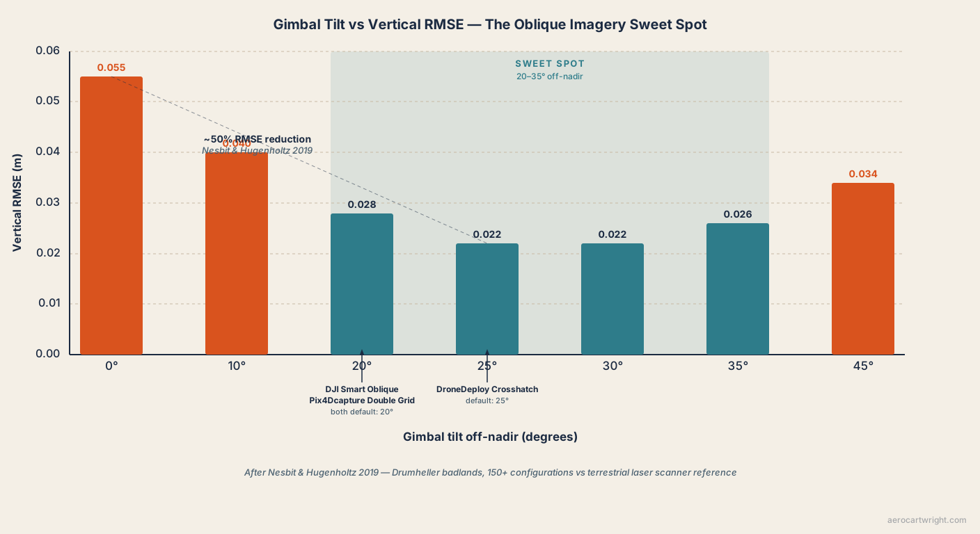
James and Robson 2014, in Earth Surface Processes and Landforms, published a workflow change that cuts doming error by up to two orders of magnitude. Nesbit and Hugenholtz 2019 measured the optimal oblique angle at 20–35 degrees off-nadir, with roughly 50 percent Root Mean Square Error (RMSE) reduction. Every major flight planner already ships the photogrammetry doming fix as a default mode: DJI Smart Oblique Capture (vendor), Pix4Dcapture Double Grid (vendor), DroneDeploy Crosshatch (vendor). The mechanism behind the trade-press argument is real. The argument that it’s an inherent ceiling on Structure from Motion (SfM) photogrammetry isn’t.
This is the doming rebuttal. The article that explains what doming is, why it happens, how to detect it, and the tolerance-by-job table lives in the existing pillar at drone map doming effect. The mechanism, detection, and tolerance content lives there, and this article doesn’t re-explain it. What follows is the case that the conventional anti-photogrammetry framing of doming is a workflow problem with a published, peer-reviewed, vendor-implemented fix.
The Claim the Industry Keeps Repeating
Heliguy’s framing is worth quoting in full because it’s the cleanest statement of the inherent-limitation argument in the trade press. Photogrammetry, the article says, “offers excellent horizontal accuracy down to 1 cm, but due to the predominantly nadir nature of capture, the vertical accuracy will be half to a third as good.”
Read the second clause carefully. “Due to the predominantly nadir nature of capture” is the load-bearing phrase. It names the mechanism correctly: parallel-axis nadir imagery can’t mathematically separate radial lens distortion from surface curvature during bundle adjustment, which produces the bowl-shaped Digital Elevation Model (DEM) error practitioners call doming. Then the framing quietly converts a flight-plan choice into a sensor limitation. Photogrammetry’s vertical accuracy is half to a third as good, the sentence reads, because of how operators fly the camera.
That’s the move. Full stop. The fix has been in the literature since 2014.
The pillar at drone map doming effect covers what doming is and how to detect it. The argument here is narrower and sharper: the published evidence doesn’t support treating doming as inherent. It supports treating it as a planning artifact with a fix that costs zero capex and a few extra minutes of flight time.
What the Bundle Adjustment Cannot Do
The mechanism, in two sentences. When every photo in an image network is taken from a near-vertical viewing angle, the bundle adjustment’s Jacobian becomes ill-conditioned with respect to the radial-distortion coefficients (k1, k2, k3) of the Brown-Conrady camera model. The optimizer can’t tell the difference between a curved lens-distortion profile and a curved ground surface, so it absorbs the lens error into the terrain shape and produces a smoothly domed DEM that fits the reprojection residuals at the cost of fitting the actual ground.
That’s the entire mechanism. The four contributors (radial-distortion misestimation, EXIF GPS elevation drift, rolling shutter, and bundle-adjustment convergence failure), the Ground Control Point (GCP)-fixes-degeneracy explanation, the DJI risk ranking, and the tolerance-by-job table all live in the existing doming-effect pillar. What matters here is the next move: once the image network includes oblique views, the optimizer can geometrically separate distortion from surface shape, the radial-distortion coefficients converge to physically correct values, and the dome flattens. The math is well posed when the geometry is.
The Published Fix — James & Robson 2014
James and Robson 2014 is the paper the trade press has not caught up with.
The setup: UAV survey simulations and real ground-based image networks, with bundle adjustment plus self-calibration enabled. The researchers constructed image networks with varying degrees of nadir-vs-oblique content, then measured the residual DEM systematic error against control. Dome magnitude tracks linearly with radial-distortion error. That is a published, characterized relationship that makes the failure mode predictable.
The headline number, paraphrased from the abstract: systematic DEM error can be significantly reduced by adding oblique images to the image network, with practical flight plans for fixed-wing or rotor UAVs that reduce DEM error by up to two orders of magnitude in the absence of control points. Two orders of magnitude. Without GCPs. On flat featureless terrain, the worst case for the mechanism.
Doming is real. James and Robson 2014 also demonstrated that adding oblique imagery to a nadir grid reduces doming-induced DEM error by up to two orders of magnitude. Doming is a planning artifact, not an inherent SfM ceiling.
The mechanism behind the fix is also why it works on existing datasets. Because dome magnitude is linear in the radial-distortion error, an existing nadir-only project can be reprocessed against the same site’s oblique imagery (even from a later separate flight) and the bundle adjustment converges to corrected distortion coefficients. The fix isn’t strictly a planning fix. It’s also a software fix, available retroactively wherever oblique imagery exists.
How Much Oblique Imagery Is Enough for Cross-Hatch Drone Mapping — Nesbit & Hugenholtz 2019
James and Robson 2014 established that the fix works. Nesbit and Hugenholtz 2019 measured the specific dose that delivers it.
The site was the Drumheller badlands in Alberta, high-relief terrain validated against terrestrial laser scanner reference. The methodology was unusual in the literature for its scale: more than 150 UAV-SfM scenarios across the full range of camera tilt from 0 degrees (nadir) to 35 degrees off-nadir, with overlap and image count varied independently.
Nesbit and Hugenholtz 2019 tested 150-plus flight configurations against terrestrial laser scanner reference. The headline number: a 20–35 degree off-nadir gimbal tilt cuts vertical RMSE (RMSEV) by roughly 50 percent.
That’s the second-most-quotable number in the literature, after James and Robson’s two orders of magnitude, and the more practitioner-useful one. It tells operators exactly how much oblique tilt to ask of the gimbal: somewhere between 20 and 35 degrees, with the bottom of the range capturing most of the benefit. A single cross-hatch pass at 25 degrees off-nadir, added to a standard nadir grid, delivers the bulk of the published improvement.
One honest caveat from the paper itself: the effects are most pronounced on high-relief terrain. On flat featureless ground, oblique imagery still helps but the magnitude is smaller, because the underlying ill-conditioning is partly from terrain texture, not just camera geometry. The fix scales with how much the site stresses the bundle adjustment. It doesn’t vanish on flat sites — the James and Robson 2014 result was measured on flat featureless terrain — but the marginal benefit per added oblique image is sensitive to relief.
The Alternative Lever — GCP Distribution (Sanz-Ablanedo 2018)
Oblique imagery is the most effective fix. GCP distribution is the second lever, and Sanz-Ablanedo et al. 2018 is the largest GCP study in the UAV photogrammetry literature.
The site: a 1,200-hectare mining area in Spain, 2,500 photos, 102 measured control points. The methodology: 3,465 different GCP-and-checkpoint combinations evaluated, with GCP counts varied from 3 to 100-plus and the balance used as independent checkpoints.
The headline finding has two parts. First, the curve. With 60 of the 102 points used as GCPs, vertical accuracy ran approximately ±16 cm. With 90 of the 102, it tightened to ±12 cm. The marginal return on additional GCPs flattens after roughly 15 well-distributed points on a typical open site, matching the Agüera-Vega 2017 benchmark of 5.8 cm RMSEV at 15 GCPs and 4.7 cm at 20 GCPs on a 17.64-hectare open field at 120 m Above Ground Level (AGL).
Second, the distribution finding — load-bearing. Corner-only placement of even ten GCPs leaves a doming residual at the project center. The bundle adjustment is anchored at the perimeter and free to curve in the interior. Same finding the existing doming-effect pillar carries forward as the “at least one GCP near project center” recommendation. The Sanz-Ablanedo evidence is the quantitative basis for it.
For step-by-step guidance on the GCP layout that satisfies both the count and distribution requirement, see how to set your own ground control points.
The Before-After Evidence Table
This is the article’s spine. Five rows of published comparison.
| Source | Nadir-only result | With oblique / cross-hatch | Reduction |
|---|---|---|---|
| James & Robson 2014 | ~0.2 m dome (realistic flight variability, no GCPs); up to ~1.3 m in idealized worst case (zero flight variability, flat featureless terrain) | ~0.02 m with a practical oblique flight plan | One to two orders of magnitude |
| Nesbit & Hugenholtz 2019 | Nadir baseline RMSE (Drumheller badlands, TLS reference) | 20–35° off-nadir oblique | ~50% reduction |
| ISPRS Archives 2023 (infrastructure) | ~0.30 m RMSE | ~0.15 m RMSE | ~2× |
| MDPI Drones 2024 (mixed-pattern, no GCPs) | 0.052 m RMSEV | 0.025 m RMSEV | Halving from a single oblique pass |
| Sanz-Ablanedo 2018 (GCP density alternative) | ±0.16 m at 60 GCPs (1,200 ha mining site) | ±0.12 m at 90 GCPs | Diminishing curve after ~15 well-distributed GCPs |
Five separate teams, four separate sites, methodologies ranging from controlled image-network simulations to terrestrial laser scanner (TLS)-referenced field surveys. The reduction direction is consistent. Magnitudes vary with site relief, overlap, and starting accuracy, but no row in the published literature shows nadir-only outperforming a properly oblique-augmented capture on a site where oblique imagery is geometrically meaningful.
The MDPI Drones 2024 row deserves a separate callout. A single perpendicular oblique pass added to a nadir grid, with zero GCPs, halved the RMSEV from 5.2 cm to 2.5 cm. The marginal cost of the fix: one extra battery, and roughly fifteen minutes of flight time.
Your Flight Planner Already Implements This
The vendor stack has already conceded the argument. Three major flight-planning apps ship cross-hatch or oblique modes as default options, and their published angles cluster inside the Nesbit and Hugenholtz sweet spot.
DJI Smart Oblique Capture (vendor)
DJI’s Smart Oblique Capture pattern, available on the Mavic 3 Enterprise (M3E) and the Zenmuse P1 mounted on the Matrice 300, 350, and 400 platforms, rotates the gimbal between five angles per pass: nadir plus four obliques tilted approximately 20 degrees off-nadir in the north, east, south, and west directions. One flight delivers the full oblique block that previously required five separate missions. The gimbal range supports manual tilt up to 45 degrees off-nadir, putting the maximum-doming-reduction angle inside reach for operators who want to push past the 20-degree default.
Pix4Dcapture Double Grid (vendor)
Pix4Dcapture’s Double Grid mission flies two perpendicular passes at the same altitude. Camera tilt is measured from horizontal, so Pix4D’s default of 70 degrees tilt is 20 degrees off-nadir. The range is configurable from 45 to 80 degrees tilt (10 to 45 degrees off-nadir). Side overlap defaults to 70 percent. Safe-mode triggering (stop at each waypoint) is required for survey-grade accuracy. For deep doming work on featureless sites, operators can manually tilt to 55–60 degrees (30–35 degrees off-nadir) and stay inside Nesbit and Hugenholtz’s sweet spot.
DroneDeploy Crosshatch and Enhanced 3D (vendor)
DroneDeploy’s Crosshatch pattern flies perpendicular passes and captures imagery at a 65-degree camera angle: 25 degrees off-nadir, the closest to the Nesbit and Hugenholtz sweet spot of the three major platforms. Enhanced 3D extends Crosshatch with a Perimeter 3D circuit at oblique angle. Live Map must be disabled during Crosshatch, and DroneDeploy recommends a 1,000-image ceiling per Enhanced 3D mission.
When DJI ships Smart Oblique Capture with a default 20° off-nadir tilt and Pix4Dcapture’s Double Grid does the same, the vendor stack has already conceded the argument. The doming fix is in the products you already own.
The mission-planning workflow that ties all three vendor defaults together, including the cross-hatch toggle, the GCP layout, and the checkpoint-validation step, is covered in the drone mapping mission planning checklist.
Self-Calibration — Software Defaults and When to Override
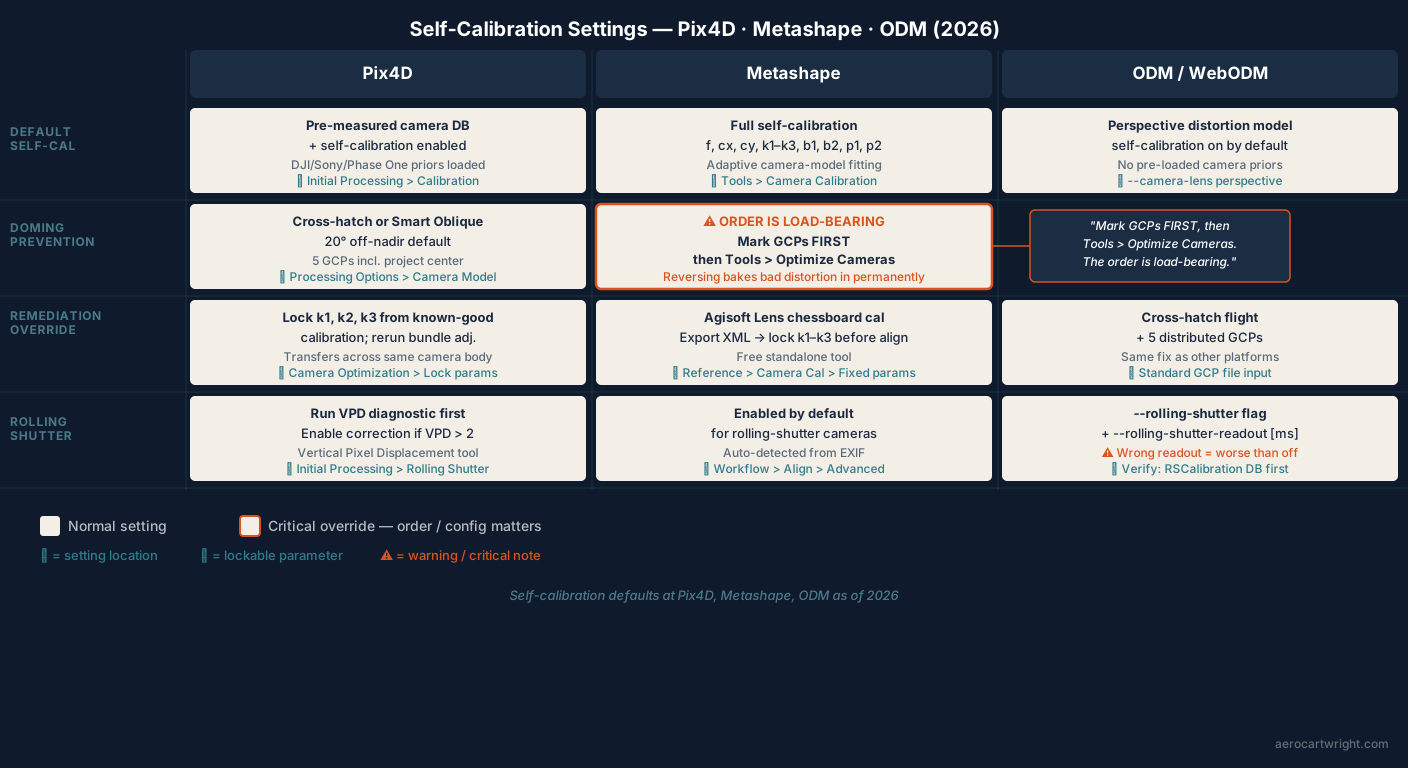
The flight pattern is half the fix. Software settings are the other half. All three major processors enable self-calibration by default; each has documented mitigations when the dataset still domes.
Pix4Dmapper / Pix4Dmatic (vendor)
Pix4D’s internal camera database loads pre-measured radial-distortion priors for common DJI, Sony, and Phase One cameras. Rolling shutter correction sits under Initial Processing > Calibration; enable it when the built-in Vertical Pixel Displacement (VPD) tool reports a value greater than 2.
The doming-remediation override: in Camera Optimization, lock the individual k1, k2, and k3 coefficients to values from a known-good calibration on the same camera body, then rerun. This works when an earlier project on the same airframe produced a clean DEM and the current dataset on the same body is doming. The calibration values transfer.
Agisoft Metashape
Metashape’s default is full self-calibration with adaptive camera-model fitting (f, cx, cy, k1, k2, k3, b1, b2, p1, p2 all estimated). The workflow order is load-bearing, and reversing it is the single most common cause of operator-induced doming in Metashape projects: mark GCPs in images first, then run Tools > Optimize Cameras. Reverse that order (optimize before adding GCPs) and the bundle adjustment bakes an unconstrained distortion estimate into the model that subsequent GCP control cannot fully correct.
For pre-calibration, Agisoft Lens (free standalone) generates parameters from a chessboard target. Export as XML, then load via Reference > Camera Calibration and lock k1, k2, k3 before alignment.
OpenDroneMap / WebODM (vendor)
ODM enables self-calibration by default with a perspective distortion model. Rolling shutter correction is the --rolling-shutter flag paired with --rolling-shutter-readout [ms]. The community-maintained readout database lives at opendronemap.github.io/RSCalibration.
The critical gotcha: an incorrect rolling shutter readout time makes results worse, not just less accurate. One community analysis found that disabling rolling shutter correction entirely outperformed using a mismatched readout. Verify the readout for the specific camera body before enabling the flag.
ODM has no fixed-parameter lock in the WebODM web UI. Pre-calibrated intrinsics must be passed via the --cameras JSON in the command-line interface. On nadir-only datasets, ODM is as susceptible to doming as any commercial pipeline. The same fix (cross-hatch plus five distributed GCPs) applies.
Worked Example — Same Site, Two Workflows
The before-after table is the literature. This is what the same operator on the same site would see by changing only flight pattern and GCP layout. Both scenarios are composed from the published literature. They aren’t a single proprietary AeroCartwright measurement.
Scenario A — Site X, 10-hectare flat agricultural field, DJI Mavic 3E, 100 m AGL, nadir-only single grid, self-calibration on, four corner GCPs. Expected RMSEV 30–45 cm with a center-dome residual of 20–30 cm. Horizontal RMSE (RMSEH) 4–6 cm. The orthomosaic looks clean; the DEM is wrong by roughly a foot at the project center. Matches James and Robson 2014’s worst-case framing and the Salach 2018 vegetation-free baseline.
Scenario B — Same site, same hardware, same overlap, DroneDeploy Crosshatch at 25 degrees off-nadir (vendor default), self-calibration on, five GCPs including one near the project center. Expected RMSEV 3–5 cm with no detectable doming residual. RMSEH 3–5 cm. Matches Agüera-Vega 2017’s 15-GCP open-field benchmark and Nesbit and Hugenholtz 2019’s 20–35 degree finding.
The choice between Scenario A and Scenario B is workflow, not platform. Same drone, same processor, same flight altitude, same overlap setting. The only differences: the cross-hatch toggle in the flight planner and the GCP layout. The literature says the second workflow is one to two orders of magnitude more accurate on the deliverable that matters. Cost differential: one extra battery and one extra GCP target. For the broader treatment of drone survey accuracy budgets, see the drone survey accuracy reference.
When Doming Persists (Honest Counter-Cases)
The published fix is not universal. Five scenarios put the cross-hatch-plus-oblique workflow out of bounds or render it insufficient. The rebuttal only holds if the boundary is honest.
-
Single-strip nadir corridors. Powerline, pipeline, narrow-road, and rail-corridor missions flown as a single 30-metre-wide strip lack enough cross-track image diversity for oblique additions to help much. A perpendicular cross-flight at corridor width is geometrically constrained; the corridor itself is too narrow for the bundle adjustment to gain meaningful new convergence angles. Dedicated corridor mapping uses a 3-strip parallel plus oblique fan-out (possible, but rarely flown outside specialist corridor missions).
-
Very high-altitude small-object datasets. When the imaged object spans a small fraction of the image frame and the platform is high enough that even oblique angles produce only narrow convergence, the bundle adjustment cannot gain enough geometric leverage from oblique imagery to fully resolve the distortion-vs-surface ambiguity. This is close-range industrial photogrammetry territory more than mainstream drone mapping, but it bites high-altitude tower or chimney inspections.
-
Wrong intrinsic camera model. Fisheye lenses processed as perspective, or perspective lenses processed as fisheye. The bundle adjustment cannot recover from a fundamentally wrong distortion model regardless of how much oblique content sits in the network. Verify the intrinsic model matches the lens before processing.
-
Sub-cm geomorphic change detection. Carbonneau and Dietrich 2017 (Earth Surface Processes and Landforms, DOI 10.1002/esp.4878) showed that even the oblique-fixed photogrammetry workflow retains a residual systematic component that matters when the deliverable is sub-centimetre geomorphic change between repeat surveys. For research-grade change detection, the residual must be modelled and removed in post-processing; the James and Robson fix gets most of the way but not all of the way.
-
Stale pre-calibration on consumer DJI cameras. Lens distortion shifts with sensor temperature. Community measurements report roughly 5 percent k1 drift cold-to-warm on consumer DJI hardware. A pre-calibration done on a cold airframe and locked through a warm flight reintroduces a residual that oblique imagery cannot remove. Either recalibrate at operating temperature or stay with thermally stabilized self-calibration on a well-conditioned image network.
A 2025 MDPI ISPRS International Journal of Geo-Information study added a sixth case as honest counter-evidence: on a small flat GCP-dense accident-scene site flown at 30 m AGL, nadir-only delivered the lowest RMSE (1.7 cm) and oblique imagery did not improve the result. When the site is small, the camera is well-calibrated, the GCPs are dense, and the altitude is low, the bundle adjustment is sufficiently constrained without oblique geometry. The fix is dose-dependent; some sites have already received the dose by other means.
For sites where leaf-on or leaf-off conditions complicate the oblique-imagery rationale (vegetation can obscure tie points at low gimbal angles) see leaf-on vs leaf-off drone mapping. And where vertical structure (towers, façades, bridge undersides) drives the oblique-imagery requirement past the simple cross-hatch case, vertical structure drone mapping covers the extended flight patterns.
Decision Tree
Two cases. Pick the one that matches the position you are in.
Case 1: You are planning a flight and need a doming-free DEM.
- Use Cross-Hatch / Double Grid / Smart Oblique mode in your flight planner. Set gimbal tilt to 25–30 degrees off-nadir. Maintain 75 percent front overlap and 65 percent side overlap.
- Lay out 5 GCPs minimum (four corners plus one near project center), with +1 GCP per 25 acres beyond the first 25. Do not corner-only.
- Withhold 3+ surveyed checkpoints from processing for independent residual validation (small-project floor; the ASPRS Edition 2 (2024) default is 30 checkpoints, capped at 120 for larger sites — disclose the floor on the deliverable).
- In Metashape: mark GCPs first, then Tools > Optimize Cameras. In Pix4D: verify Vertical Pixel Displacement before enabling rolling shutter. In ODM: verify rolling shutter readout against the RSCalibration database before passing the flag.
Case 2: You inherited a nadir-only dataset that is doming.
- If oblique imagery from any later flight over the same site exists, add it to the same project and reprocess with self-calibration on.
- If a known-good camera calibration from another flight on the same body exists, lock k1, k2, k3 from that calibration and reprocess.
- If neither exists and a return-to-site is impossible, last-resort polynomial trend-surface removal can remove the systematic component. This treats the symptom, not the cause; flag the deliverable as having received post-processing detrending.
The Real Argument
Doming gets repeated as inherent because it’s load-bearing for the LiDAR sales pitch. If photogrammetry has a structural vertical-accuracy ceiling, the 2–3× cost premium for drone LiDAR is justified across most of an operator’s job book. If the ceiling is a workflow artifact, the premium only applies to the specific job types where LiDAR earns it: canopy penetration, bare-earth Digital Terrain Models (DTMs) under vegetation, textureless surfaces, low-light environments, multi-return wire-versus-vegetation separation. The full set of those scenarios is bounded and named in the lead piece, where photogrammetry beats LiDAR on accuracy: the open-terrain evidence, and adjacent siblings cover the free orthomosaic LiDAR-only flights leave behind and the stockpile case where LiDAR doesn’t pay.
The published evidence doesn’t support the inherent-ceiling framing: Wackrow and Chandler 2008 on the mechanism, James and Robson 2014 on the two-orders-of-magnitude fix, Nesbit and Hugenholtz 2019 on the 20–35 degree sweet spot, Sanz-Ablanedo 2018 on the GCP-distribution alternative. The vendor stack doesn’t support it either. The fix is shipped, the angles are defaulted to the right range, and the software has documented overrides for the cases where self-calibration needs help. The trade-press argument that photogrammetry has half-to-a-third the vertical accuracy of LiDAR due to the predominantly nadir nature of capture names a fixable workflow choice and dresses it up as an inherent property.
The mechanism is real. The argument that it justifies a 2–3× hardware premium across general open-terrain mapping isn’t. The full head-to-head on this point — when LiDAR earns its premium and when it doesn’t — sits at the LiDAR vs photogrammetry pillar.
Frequently Asked Questions
Can doming actually be fixed with flight planning?
Yes. James and Robson 2014 (Earth Surface Processes and Landforms 39(10):1413–1420) measured up to a two-orders-of-magnitude reduction in DEM error when oblique imagery is added to a nadir grid — published, peer-reviewed, repeatedly replicated. Nesbit and Hugenholtz 2019 quantified the practitioner number: a 20–35 degree off-nadir gimbal tilt cuts RMSEV by roughly 50 percent. Every major flight planner — DJI Smart Oblique, Pix4Dcapture Double Grid, DroneDeploy Crosshatch — already implements the fix as a default mode.
What is the difference between this article and the existing doming effect pillar?
The pillar at drone map doming effect describes what doming is, why it happens, how to detect it, and the job-by-job tolerance table. This article is the rebuttal to the framing that doming is inherent to photogrammetry. The mechanism content lives in the pillar; the published-fix evidence and the vendor-default cross-check live here.
How much oblique imagery is enough?
Nesbit and Hugenholtz 2019 tested 150-plus flight configurations against terrestrial laser scanner reference at the Drumheller badlands and found the sweet spot at 20–35 degrees off-nadir gimbal tilt, with roughly 50 percent RMSE reduction relative to nadir-only blocks. DJI Smart Oblique defaults to 20 degrees, Pix4Dcapture Double Grid to 20 degrees, DroneDeploy Crosshatch to 25 degrees. A single perpendicular cross-hatch pass at 25 degrees captures most of the available benefit.
Does adding more GCPs eliminate doming without oblique imagery?
Partially. Sanz-Ablanedo et al. 2018 measured the curve on a 1,200 ha mining site: 60 GCPs delivered ±16 cm vertical, 90 GCPs delivered ±12 cm — a flattening curve after roughly 15 GCPs on a typical open site. Distribution matters more than count. Corner-only placement leaves a center dome regardless of GCP density. Add at least one GCP near the project center, then add oblique imagery for the strongest combined fix.
When does doming persist despite the published fix?
Five honest counter-cases: single-strip nadir corridor mapping (powerlines, narrow roads); very high-altitude small-object datasets where the convergence angle stays narrow; wrong intrinsic camera model (fisheye processed as perspective); sub-cm geomorphic change detection where the Carbonneau and Dietrich 2017 residual matters; and stale pre-calibration where lens distortion has shifted with temperature. For practitioner cm-level survey work outside those cases, James and Robson’s published fix is sufficient.
How do I reprocess an existing nadir-only dataset to remove doming?
If you have oblique imagery from a later flight over the same site, add it to the same project and rerun bundle adjustment with self-calibration on. If you only have nadir imagery but a known-good camera calibration from another flight, lock k1, k2, and k3 in your camera optimization settings (Pix4D Camera Optimization, Metashape Reference > Camera Calibration > Fixed parameters, ODM via --cameras JSON). If you have neither, polynomial trend-surface removal is the last-resort option — but it treats the symptom, not the cause.
What rolling shutter readout do I use for ODM?
Verify the readout time for your specific camera body against the community-maintained database at opendronemap.github.io/RSCalibration before enabling --rolling-shutter. An incorrect readout makes the result worse, not just less accurate. One community analysis found that disabling rolling-shutter correction entirely outperformed using a mismatched readout time.
Sizing a survey workflow against a specific deliverable, or trying to figure out whether a doming-prone legacy dataset can be reprocessed with new oblique imagery before you re-fly the site? Reach out. AeroCartwright runs paid flight-plan and processing-workflow reviews for drone operators and engineering teams.