Part 3 of 6 in the Drone Mapping Checklist Series — one article per phase of a commercial drone survey, publishing every Friday.
The GCP That Wasn’t
An operator deploys 8 GCPs on a 30-acre site. Measures all 8 with an RTK rover. Files the coordinates in the field log. Flies the mission. In processing, he imports the GCP coordinates and starts marking targets in the imagery. Target CP-05 is nowhere to be found. It was placed at the edge of a tree line — visible from the ground, invisible from nadir at 200 feet AGL. The canopy swallowed it. Seven GCPs instead of eight. The distribution is now uneven — no control on the entire east side of the site. The ortho drifts 8 cm east in that area. The surveyor reviewing the deliverable catches it. The operator gets the call nobody wants.
Here’s the second one.
Same day, different site. An operator deploys and measures GCPs on a windy day. Targets are 12”x12” fabric squares, staked with a single pin in the center. Mid-mission, wind picks up. Two targets shift — one flips over entirely, the other rotates 45 degrees. The operator doesn’t notice from the control station 300 meters away. In processing, the target center in the imagery no longer matches the measured point location. Two GCPs now carry 5-10 cm positional errors. The processing software reports high residuals on those points, but the operator assumes it’s normal variation and forces the solution. The entire model warps around those two bad points. Deliverable rejected.
GCP deployment is the most manual, error-prone phase of a drone mapping mission. Every target you place is a potential failure point — wrong position, wrong measurement, poor visibility, physical displacement. Unlike airspace checks or flight planning, there’s no software to backstop you. No app pops up to say “CP-05 is under a tree.” No warning tells you a target flipped in the wind. You are the quality control system.
A GCP deployment checklist systematizes the process so each point is placed, measured, documented, and verified before you launch. It turns a sequence of field judgments into a repeatable procedure. This is the checklist.
How Many GCPs and Where
For the complete treatment of GCP count, distribution theory, and accuracy implications, see Ground Control Points for Drone Mapping. What follows is the practical summary — the numbers you need when you’re standing at the tailgate with targets in hand.
Minimum 5 GCPs for any project that requires georeferenced accuracy. Three defines a plane. Five gives redundancy and allows checkpoint validation — use 3 as control, 2 as checkpoints, at minimum.
| Survey Area | Recommended GCPs | Recommended Checkpoints | Total Targets |
|---|---|---|---|
| < 10 acres | 5 | 2 | 7 |
| 10-30 acres | 6-8 | 2-3 | 8-11 |
| 30-60 acres | 8-10 | 3-4 | 11-14 |
| 60-100 acres | 10-12 | 4-5 | 14-17 |
| > 100 acres | 12+ (add 1 per 10 acres above 100) | 5+ | Scale accordingly |
These counts assume standard photogrammetric processing with block adjustment. If you’re running an RTK/PPK-enabled platform with direct georeferencing, you can reduce the GCP count — but you still need checkpoints to validate accuracy. Direct georeferencing without ground truth is a claim without evidence. Don’t deliver it.
Distribution Rules
-
Perimeter coverage. Place GCPs around the perimeter of the survey area. Four corners plus midpoints of the longest sides as a baseline distribution. The edges of your photogrammetric block are where accuracy degrades fastest — control at the perimeter constrains that degradation.
-
Interior distribution. Add points in the interior to prevent the model from “dishing” or “doming” — a systematic vertical distortion that occurs when control exists only at the edges. The bundle adjustment has nothing to anchor the interior, so it flexes. One interior point per 10-15 acres of site area eliminates this.
-
Elevation diversity. On sites with relief, place GCPs at varying elevations — hilltops, valleys, mid-slopes. Control at a single elevation allows vertical drift at other elevations. If your site has 50 feet of relief and all your GCPs sit at the same contour, your vertical accuracy at the high and low points is unconstrained. Spread the control vertically.
-
Checkpoints separate from control. Checkpoints validate your accuracy. They must be independent from the GCPs used to constrain the model. Place checkpoints in different locations than GCPs — not adjacent, not in the same cluster. Spread them across the project area. If your checkpoints are clustered next to your GCPs, they test accuracy only where accuracy is already highest. That tells you nothing about the rest of the site.
-
Clear line of sight from nadir. Every target must be visible from directly above at flight altitude. This is the lesson from CP-05 and the tree canopy. Before you pin a target down, look up. If there’s a tree branch, overhead wire, building overhang, or any obstruction between the target and the sky, move the target. Walk 10 feet into the open. Lose the “perfect” position in favor of the visible one.

Target Specifications
What makes a good GCP target for drone mapping — and what makes one that looks good on the ground but fails in the air.
-
Size relative to GSD. The target must be at least 5x the ground sample distance per side to be reliably identified in imagery. At 2 cm/px GSD, that’s a 10 cm (4 inch) minimum. At 1 cm/px, 5 cm. Bigger is better for identification speed in processing — 12”x12” (30 cm) targets work well for most mapping altitudes between 200 and 300 feet AGL. At 400 feet AGL with 3-4 cm/px GSD, go to 18”x18” or larger. A target you can’t find in the imagery is a target that doesn’t exist.
-
High-contrast pattern. Black and white checkerboard, crosshair, or X pattern. The contrast must be visible against the ground surface. White targets on concrete disappear. Black targets on fresh asphalt disappear. Match the target to the ground: if the surface is light (concrete, sand, dry grass), use a dark target or a target with a dark outer pattern. If dark (asphalt, dark soil, wet vegetation), use a white-dominant pattern. The processing software needs to distinguish the target center from the surrounding pixels. If they’re the same color, you’re asking the software to find nothing.
-
Flat against the ground. Targets that curl, wrinkle, or elevate above the surface introduce measurement error. The measured point is the center of the target on the ground surface. If the target is 2 cm above the surface because the fabric is tenting over a rock or curling in the heat, your vertical measurement is 2 cm off. That’s 2 cm of error you built into the dataset yourself. Fabric targets pinned flat, painted targets, or rigid panel targets all work. Cheap vinyl banner material curls in heat — if you use it, pin it aggressively.
-
Secured against wind. Stakes, pins, rocks, tape, sandbags. The target must stay in position from deployment through the last image capture. A single center pin on fabric is insufficient in any wind above 5 mph. Pin all four corners plus the center. Or use panel targets heavy enough to resist displacement. If the wind picks up during the mission, walk out to your nearest targets and verify they haven’t moved. The two minutes that walk takes is cheaper than the refly.
-
Target material options. Propeller AeroPoints — self-measuring GNSS targets, high cost ($3,500-$5,500 for a set), eliminates manual measurement. DIY canvas or fabric — low cost, requires manual measurement, needs aggressive staking. Pre-printed vinyl targets — moderate cost, durable, good contrast, but watch for curling. Spray-painted ground marks — permanent, zero material cost, not retrievable, useful for construction sites where targets would be driven over. Choose based on budget, retrieval requirements, and how many days you’ll reuse the points.
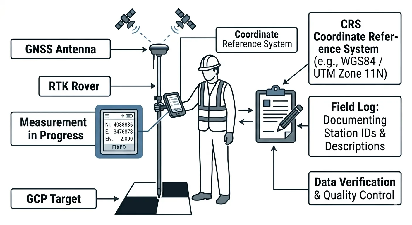
Measurement Procedure
The single most common source of GCP error is measuring in the wrong coordinate reference system. Not a bad GNSS fix. Not a multipath reflection. A settings error. The operator selects the wrong datum, the wrong projection zone, or the wrong vertical reference — and every measurement shifts by a consistent offset that looks clean in the field but destroys the deliverable in processing.
-
Verify the CRS before the first measurement. Open the RTK rover or total station configuration. Confirm the coordinate reference system matches the project specification — horizontal datum, vertical datum, projection, units. NAD83(2011) is not the same as NAD83(CORS96). State Plane zone 0501 is not zone 0502. Ellipsoidal heights are not orthometric heights — the difference between them varies from roughly 25 to 55 meters across the continental US. One wrong setting and every measurement you take is internally consistent but offset from the project’s coordinate framework. This is the error that costs a full refly.
-
RTK measurement procedure. Set up the base station over a known control point or allow it to determine its position via OPUS or a static observation. Connect the rover. Wait for a fixed solution — integer ambiguity resolved. Occupy each GCP target center for a minimum of 10 seconds. Many practitioners use 30-60 seconds for averaging, which reduces noise and catches intermittent float drops. Record the position only when the solution shows “Fixed” with PDOP under 2.0 and satellite count above 12. If the solution drops to float during occupation, discard and re-observe. A float solution is not survey-grade. Don’t treat it as one.
-
Total station measurement procedure. Set up over a control point with known coordinates. Backsight to a second control point. Verify the closure is within tolerance — typically 0.01 ft or better for engineering surveys. Measure each GCP target center with the prism or reflectorless shot. Log the same metadata as RTK. Total station measurements don’t depend on satellite geometry, so PDOP and satellite count don’t apply — but verify the instrument calibration is current and the atmosphere correction is set for ambient conditions.
-
PPK measurement via base station. If measuring GCPs with a PPK solution, ensure the base station is logging raw GNSS observations simultaneously with the rover. Post-process the base station data against a CORS station to determine its precise position. Apply the corrected base position to all rover measurements. This requires post-processing before coordinates are final — you won’t have confirmed coordinates in the field. Plan accordingly: you can’t verify your measurements against the project CRS until you’re back at the office.
For a full comparison of RTK vs PPK positioning methods and when to use each, see RTK vs PPK for Drone Mapping.
- Measure the same point you’ll identify in the imagery. This sounds obvious. It isn’t always practiced. The measured point must be the exact center of the target — the intersection of the crosshair, the center of the checkerboard, the nail under the X. If you measure a point 3 cm from the target center because the rover pole was tilted, you have a 3 cm error in every axis. Level the pole. Center the tip. Take the time.
Photo Documentation
This is the step most operators skip. It is also the step most operators wish they hadn’t skipped when they’re sitting in front of processing software at 10 PM trying to figure out which cluster of pixels is CP-07.
-
Close-range photo of each target. Photograph each GCP target with a handheld camera or smartphone showing the target pattern, the center point, and any marking — ID label, stake, paint mark. Include a scale reference in the photo: a survey rod, tape measure, or known-size object. This photo identifies the target during processing when you’re trying to match CP-07 in the imagery to CP-07 in your coordinate list. It also proves the target was intact and properly centered at the time of measurement.
-
Wide-angle context photo. Step back 10-20 feet and photograph the target in its surroundings. Capture nearby features — fence lines, road edges, vegetation, structures, anything distinctive. When you’re clicking through 400 aerial images trying to find a 12-inch target on a 30-acre site, the context photo tells you exactly where to look. “CP-03 is next to the fire hydrant at the southwest corner of the parking lot” saves 15 minutes of searching.
-
Vertical overhead photo. For targets 18 inches or larger, take a photo from directly above looking down. Hold the phone at arm’s length over the target center. This shows the exact target center and its condition — flat, wrinkled, displaced, partially obscured by grass or debris. Compare this to the nadir aerial imagery during processing to verify target identification. If the overhead photo shows a clean crosshair and the aerial image shows a distorted blob, the target moved.
-
Photo file naming. Name each photo with the point ID immediately after capture: CP-01_close.jpg, CP-01_context.jpg, CP-01_overhead.jpg. If your camera doesn’t allow in-field renaming, photograph a written label — piece of tape with the point ID written in marker — before each target’s photo set. This creates a visual separator in your photo stream. When you’re back at the office scrolling through 60 photos, those label shots are the index markers that keep everything organized.
Field Log
Every GCP gets a record. Every record contains the same fields. No exceptions, no shortcuts, no “I’ll remember that one.”
| Field | Example | Notes |
|---|---|---|
| Point ID | CP-01 | Unique, sequential. CP prefix for control, CK for checkpoints |
| Type | GCP or Checkpoint | Designated before measurement, not after |
| Northing / Latitude | 4,372,891.234 m | CRS and units must match project spec |
| Easting / Longitude | 503,221.567 m | |
| Elevation / Height | 1,723.45 m | Specify: ellipsoidal or orthometric |
| Vertical datum | NAVD88 (Geoid 18) | Critical — ellipsoidal vs orthometric differs by meters |
| CRS / EPSG | NAD83(2011) / State Plane CO North / EPSG:6428 | Full specification, not shorthand |
| Measurement method | RTK Fixed | Fixed, Float, Static, TS (total station) |
| Occupation time | 30 sec | Minimum 10 sec for RTK |
| PDOP | 1.2 | Below 2.0 preferred |
| Satellite count | 18 | Minimum 12 for reliable fixed solution |
| Date/Time | 2026-04-27 08:45 MDT | UTC preferred for GNSS correlation |
| Notes | Adjacent to manhole rim, NE corner of site | Any relevant context for relocation or identification |
Keep this log in a field notebook AND digitally. The digital file lives on the rover’s data collector or a tablet. The field notebook is the backup you hope you never need. Photograph the notebook page at the end of the day. If the digital file corrupts, you have the photo. If the notebook gets wet, you have the digital file. Two independent records. One data set.
The point ID convention matters. Use CP- for control points and CK- for checkpoints from the start. Don’t deploy 10 targets, measure them all, and decide later which ones are control and which are checkpoints. That decision affects placement strategy. Checkpoints should be in different locations than GCPs — designate them before you walk into the field, not during processing when you realize your accuracy report needs validation points.
Download the GCP Deployment Checklist PDF
Get the printable GCP deployment checklist as a PDF. Every step from planning through pre-flight verification — formatted for the field, not the office.
Download the GCP Deployment Checklist →
The download page also links to a free bonus: a printable GCP Field Log with the Required Fields reference and 20 blank entry rows for recording control points and checkpoints in the field. No signup required.
This is part 3 of the 7-part Drone Mapping Checklist Series. Previous: Mission Planning Checklist. Next: Post-Flight QA Checklist — what to verify before you leave the site.