Part 5 of 6 in the Drone Mapping Checklist Series — one article per phase of a commercial drone survey, publishing every Friday.
The Coordinate System That Cost a Client
An operator processes a 50-acre site survey. Imports 600 images from an RTK-enabled drone. Alignment succeeds — 98% of images calibrated, clean tie point cloud. GCPs integrated. Residuals look reasonable: 1.8 cm horizontal, 2.6 cm vertical. Dense point cloud generates overnight. Orthomosaic exported. DSM exported. Contours generated at 1-foot intervals. Quality report shows 2.1 cm horizontal RMSE, 3.4 cm vertical RMSE. Everything checks out.
He delivers the dataset to the client’s civil engineering firm. Their CAD technician imports the orthomosaic into Civil 3D. It lands 30 meters off from their existing control network. Everything is shifted — horizontally and vertically. The entire dataset is unusable.
The reason: the operator processed in WGS84 ellipsoidal heights — the GPS default — and delivered to a firm working in NAD83(2011) / State Plane with NAVD88 orthometric heights using Geoid 18. The horizontal shift is the datum transformation difference between WGS84 and NAD83(2011). The vertical shift is the geoid-ellipsoid separation — about 25-30 meters in Colorado. The RMSE numbers were valid. The internal consistency was fine. But the data was in the wrong coordinate framework. The quality report showed accuracy relative to the GCPs, which were also measured in WGS84. Everything was self-consistent and completely wrong for the client’s use.
Second scenario. Same processing workflow, correct CRS this time, but the operator didn’t review the quality report’s checkpoint residuals. Three of five checkpoints showed 15+ cm vertical residuals — far outside the 5 cm project specification. The GCP residuals were clean because the model was warped to fit the control points. That’s what GCPs do — they constrain the model to their positions. The checkpoints — independent validation points not used to constrain the model — revealed the actual accuracy. The operator delivered without reviewing them. The client’s surveyor ran an independent check survey and found the same 15 cm offset across the site. Deliverable rejected. Reprocessing required. Credibility damaged.
Both errors are caught by a drone mapping processing checklist. First: CRS verification before import. Second: checkpoint review before export. Neither takes more than two minutes. Both prevent deliverable rejection.
This is the checklist.
Project Setup and Coordinate System
The most critical step in the entire processing workflow. Get this wrong and nothing downstream matters. Every pixel, every point, every contour line inherits the coordinate system you set at the start.
-
Verify CRS before importing images. Open your processing software — Pix4D, Metashape, WebODM, DJI Terra. Set the project coordinate reference system BEFORE importing images. Match to the project specification exactly: horizontal datum, projection, zone, units, vertical datum, geoid model. Do not guess. Do not assume. Pull the spec document and type what it says. Common traps:
-
NAD83 vs NAD83(2011) — these are different realizations with measurable differences. NAD83(2011) is the current adjustment. Using the original NAD83 realization introduces up to 1-2 meters of positional error depending on your location. Your software lists both. Pick the right one.
-
State Plane feet vs international feet — Colorado, for example, uses US survey feet. The difference between US survey feet and international feet is 2 parts per million. On a 500-foot baseline, that’s 1 mm — invisible. On a 10-mile corridor, it’s 3 cm. Measurable. Wrong. The distinction matters for corridor projects, utility mapping, and anything that ties into existing survey control.
-
Ellipsoidal heights vs orthometric heights — the difference is the geoid undulation, typically 20-35 meters in the continental US. Process in ellipsoidal, deliver in orthometric, and your surface model sits 30 meters above the real ground. The client’s CAD software won’t zoom to it. Their design surface won’t intersect it. Nothing works.
-
UTM zone boundaries — if your site straddles a zone boundary, pick one zone and document it. Processing half the site in Zone 13N and half in Zone 12N creates a seam that no amount of post-processing fixes cleanly. Pick the zone that contains the majority of the site. Note the choice in your processing log.
-
-
Set the image coordinate system. Images from RTK/PPK drones store positions in WGS84 geographic coordinates — latitude, longitude, ellipsoidal height. Your project CRS may be NAD83(2011) State Plane in US survey feet with NAVD88 orthometric heights. These are not the same thing. Tell the software what CRS the image positions are in (usually WGS84) and what CRS the project output should use. The software handles the transformation — but only if both systems are specified correctly. If you leave the image CRS as “same as project,” the software assumes the embedded coordinates are already in the project CRS. They’re not. The transformation never happens. Your output shifts.
-
Set the GCP coordinate system. If your GCPs were measured in a different CRS than the project output — common when base station coordinates are in a local datum or when you’re transforming from a measurement CRS to a delivery CRS — specify the GCP coordinate system separately. Most software supports importing GCPs in their native CRS and transforming automatically. Don’t manually convert coordinates in a spreadsheet. That’s where transcription errors and wrong conversion factors live. Let the software do it. Cross-reference: this is why the field log from the GCP deployment checklist records the full CRS specification for every measurement session.
-
Set output CRS and format. Confirm the output CRS matches the client’s deliverable specification. Confirm file formats — GeoTIFF for ortho and DSM, LAS/LAZ for point clouds, DXF or SHP for contours. Confirm units. Set these now, not at export time, so you can verify coordinate values during processing.

Image Import and Initial Alignment
The first quality gate. If alignment fails or shows poor metrics, stop and diagnose before proceeding. Every step after this builds on the alignment result.
-
Import all images for the project. Verify image count matches the field record. If the post-flight QA checklist recorded 847 images captured and you’re importing 843, four images are missing. Find them. Check the SD card for read errors. Check for images that failed to copy. Four missing images in a 70% overlap grid might not cause visible problems. Four missing images in a tight corridor with 60% sidelap will leave a hole.
-
Run initial alignment. “Align Photos” in Metashape, “Initial Processing” step 1 in Pix4D, or the equivalent in your software. The algorithm matches features across overlapping images, computes tie points, and estimates camera positions through bundle adjustment. This step determines the geometry of your entire project.
-
Check alignment rate. Target: 95%+ of images aligned. Below 95%, investigate. Below 90%, stop and diagnose before continuing. Common causes of alignment failure:
- Water bodies, snow, or homogeneous surfaces — low texture means the feature-matching algorithm finds nothing to lock onto. Increase overlap on the next mission for these areas. For the current dataset, try adjusting alignment settings to use more keypoints per image.
- Motion blur — blurred images produce unreliable tie points. Remove them from the dataset and re-align. Check the post-flight QA log to confirm shutter speed was appropriate for ground speed.
- Insufficient overlap in specific areas — if a strip of images at the edge of the flight area failed to align, verify the post-flight overlap map didn’t flag a gap you overlooked.
- Wrong camera model — verify the software detected the correct camera and lens. Mixed datasets from different cameras or drone platforms need separate camera groups in the alignment.
-
Review reprojection error. The mean reprojection error should be below 1.0 pixels for survey-grade work. Above 1.5 pixels indicates systematic problems — bad tie points, incorrect camera calibration parameters, or mixed datasets that weren’t properly separated. In Metashape, use gradual selection to remove high-error tie points: filter by reprojection error, remove the worst 10%, then run Optimize Cameras. Repeat until the mean drops below 1.0. In Pix4D, review the quality report’s initial processing section for the median reprojection error and the number of calibrated images.
-
Review camera calibration estimates. The software estimates internal camera parameters during alignment — focal length, principal point offset, radial distortion coefficients (K1, K2, K3), and tangential distortion (P1, P2). Compare the estimated focal length against the manufacturer’s specification. A deviation greater than 5% signals calibration instability, usually caused by insufficient overlap, poor image geometry, or a dataset too small for reliable self-calibration. If the estimated focal length is 8.2 mm on a camera spec’d at 8.8 mm, something is wrong. Flag it. Don’t proceed with a bad calibration — the dense point cloud will inherit every error the alignment carries.
GCP Integration
Where field data meets processing data. This step either validates or invalidates your entire dataset. Take your time.
-
Import GCP coordinates. Use the coordinates from the field log — not from memory, not from a different project. Verify the CRS matches what you specified in the import dialog. If the field log records coordinates in NAD83(2011) State Plane Colorado North in meters, import them as NAD83(2011) State Plane Colorado North in meters. Do not mentally convert units. Do not round. Copy the coordinates exactly as measured.
-
Designate control points and checkpoints. Before marking, decide which points are GCPs (used to constrain the model) and which are checkpoints (used to validate accuracy independently). A minimum of 2 checkpoints. More is better. Checkpoints must not be used in the optimization — they serve as your independent accuracy test. If you use every measured point as a GCP, you have no way to validate accuracy except by checking your own homework. That’s not validation.
-
Mark GCP targets in images. For each GCP, identify the target center in at least 5-8 images. More is better — 10-15 marks per GCP tightens the solution. Click the center of the target pattern. Not the edge. Not the pin. The center. This step is tedious and demands precision. Sloppy marking introduces 1-3 pixels of error per mark, which propagates directly into the georeferencing residuals. A 2-pixel marking error at 2 cm/px GSD is 4 cm of positional uncertainty per mark. At survey-grade specs, that’s your entire error budget consumed by clicking in the wrong spot.
-
Run optimization with GCPs. After marking all GCPs (not checkpoints), run the bundle adjustment optimization. The software re-computes camera positions and orientations constrained to the GCP coordinates. This is the step that georeferences the model to real-world coordinates. In Metashape, this is “Optimize Cameras” with the control points enabled. In Pix4D, this is the “Reoptimize” step after GCP marking.
-
Review GCP residuals. After optimization, check the residual on each GCP. The residual is the distance between the GCP’s measured coordinate and the GCP’s position in the optimized model.
| Accuracy Class | Max Horizontal Residual | Max Vertical Residual |
|---|---|---|
| Survey grade (2-5 cm) | < 2.0 cm | < 3.0 cm |
| Engineering grade (5-10 cm) | < 5.0 cm | < 7.0 cm |
| Planning/volumetric (10-20 cm) | < 10.0 cm | < 15.0 cm |
-
Investigate outliers. If any single GCP has a residual more than 2x the average of the others, investigate before accepting the solution. Common causes:
- Wrong target identified in imagery — you marked a paint spot or debris instead of the actual target
- Target displaced during flight — wind, vehicle traffic, or foot traffic moved the target between measurement and image capture
- Measurement error in the field — a float solution recorded as fixed, or a single-epoch measurement instead of a proper occupation
- Wrong point ID in the coordinate file — CP-03 and CP-05 transposed in a spreadsheet
Don’t force a bad GCP into the solution. Disable it and re-optimize. A clean solution with 6 GCPs beats a contaminated solution with 7. Every time.

Dense Point Cloud and Mesh Generation
The compute-intensive step. Settings affect both quality and processing time — sometimes dramatically.
- Select quality settings by project type. Match the processing quality to the deliverable requirement. Higher quality costs processing time.
| Setting Level | Processing Time | Use Case |
|---|---|---|
| Ultra High / Original | 4-12x longer | Research, heritage documentation, sub-cm detail required |
| High | 2-4x baseline | Survey-grade mapping, engineering deliverables |
| Medium | Baseline | Volumetrics, planning-grade orthos, large area coverage |
| Low | 0.5x baseline | Quick previews, preliminary checks, time-critical deliverables |
For most survey and engineering projects, High is the correct setting. Ultra High produces marginal accuracy improvement at massive time cost. Reserve it for projects where sub-centimeter point cloud detail justifies 4-12x longer processing.
-
Set depth filtering. Aggressive depth filtering removes noise but also strips fine detail — thin features, vegetation edges, fence wires. Mild filtering preserves detail but introduces more noise points that float above or below the true surface. For topographic mapping: moderate or aggressive. For vegetation studies or structural inspection: mild. For construction volumetrics on cleared ground: aggressive. The wrong setting doesn’t ruin the dataset, but it creates unnecessary work in post-processing — either cleaning noise or recreating lost detail.
-
Inspect the point cloud. After generation, visually inspect the dense point cloud. Rotate through the model. Look for:
- Floating points — noise clusters above the true surface, common over water, glass, or highly reflective surfaces
- Gaps in coverage — holes where no points were generated, indicating areas where the alignment failed or overlap was insufficient
- Systematic errors — warping, dishing, or doming. These are vertical distortions that curve the model into a bowl or a dome shape, caused by poor GCP distribution, insufficient camera self-calibration, or a weak image network geometry
Cross-section the point cloud along known flat surfaces. A parking lot, a warehouse roof, a freshly graded pad — these should produce flat cross-sections. If you see curvature in a surface you know is flat, you have a systematic error. Go back to the GCP network. Check the distribution. Check for a bad GCP coordinate. Check the camera calibration. Don’t proceed with a curved model.
-
Build mesh if required. 3D mesh is needed for textured models, volume calculations on irregular surfaces, and some visualization deliverables. Build the mesh from the dense point cloud, not from the sparse tie points. Set face count appropriate to the deliverable — full resolution for high-detail 3D models, decimated for web viewing or CAD import. A 50-million-face mesh brings Civil 3D to a crawl. Know your client’s software limitations.
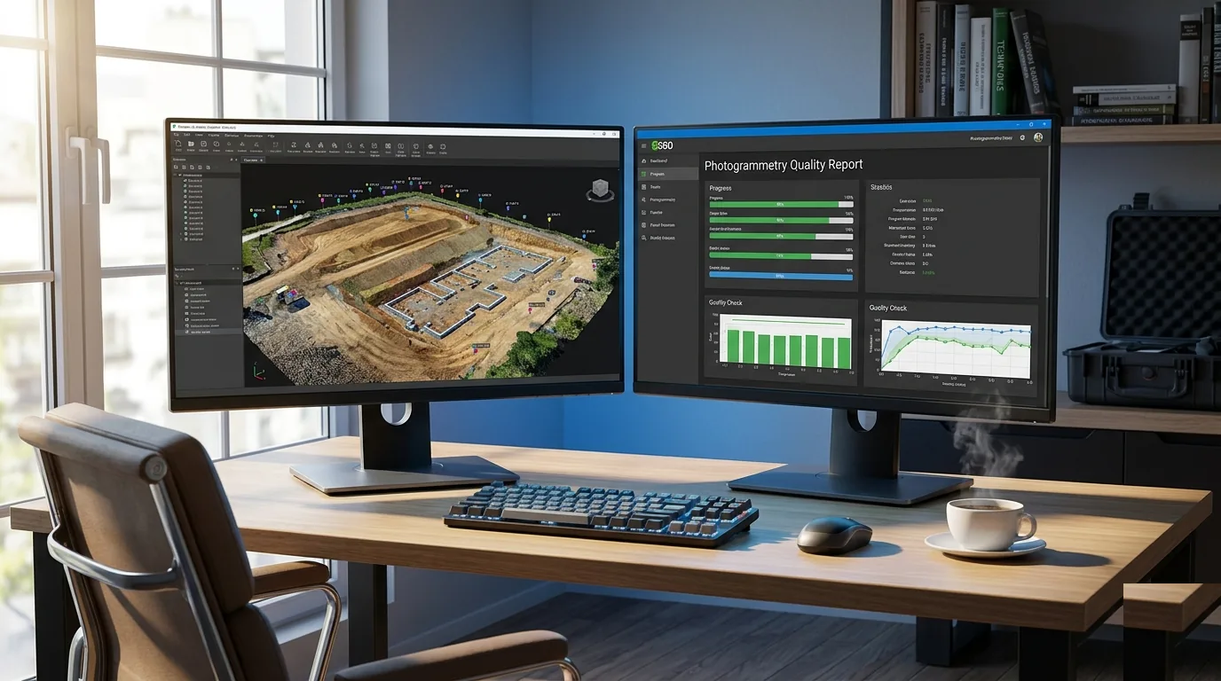
Quality Report Review
The quality report is the document that makes your deliverable defensible. It transforms “we think the data is accurate” into “the data meets specification X, validated by Y.” Review it before exporting anything.
-
GCP residuals summary. Verify all GCP residuals fall within the thresholds from the GCP Integration section. The report should state total RMSE prominently. Record it: “Horizontal RMSE: X.X cm. Vertical RMSE: X.X cm.” These numbers go on your accuracy statement, your metadata, and your deliverable documentation. They are the numbers the client’s surveyor will check first.
-
Checkpoint residuals. This is the independent accuracy validation — the number that actually matters. Checkpoints were not used to constrain the model. Their residuals show how accurate the model is in areas not anchored by GCPs. Checkpoint RMSE should be within the project accuracy specification. If checkpoint residuals are significantly worse than GCP residuals — more than 2x — the model is overfitting to the control points. This means the GCP distribution is too sparse, the camera calibration is unstable, or a GCP coordinate is wrong. The model bends to fit the GCPs and drifts everywhere else. Fix the cause. Reprocess.
-
Overlap statistics. The quality report should show effective overlap across the survey area. Target: 5+ images per ground pixel for survey-grade work. Areas with fewer than 3 images of effective overlap are accuracy weak spots — the geometry is thin, and the point cloud in those areas is less reliable. If these areas fall within the deliverable boundary (not just the flight buffer), flag them in your deliverable documentation. The client needs to know where accuracy may degrade.
-
Camera calibration parameters. Compare final calibrated parameters against initial estimates and manufacturer specs. Stable calibration indicates a healthy dataset. If the focal length shifted significantly during optimization or distortion coefficients diverge from manufacturer values, the calibration may be unreliable. Common with small datasets (under 100 images) or narrow corridor projects lacking geometric diversity for self-calibration.
-
Coverage map. Review orthomosaic and DSM coverage extents. Verify no holes exist within the survey boundary. Edge holes are expected — that’s the buffer zone. Interior holes indicate processing failures, data gaps, or silent alignment failure. If interior holes exist, determine the cause and whether a refly is needed or the gap falls outside deliverable scope.
-
Save the quality report. Export or save the full quality report as a PDF. Archive it with the project files. This report is your evidence. If a client questions accuracy six months from now, the quality report is your defense. If a surveyor challenges your numbers, the quality report contains the math. Don’t discard it. Don’t summarize it. Keep the original.

Cross-reference: for a detailed treatment of accuracy validation methodology and what makes a quality report defensible, see Understanding Survey Accuracy for Drone Mapping.
The Complete Processing Checklist
Print this. Run through it every time. Skip nothing.
Project Setup
| # | Item | ✓ |
|---|---|---|
| 1 | Project CRS set to match deliverable specification (datum, projection, zone, units) | ☐ |
| 2 | Vertical datum and geoid model specified correctly | ☐ |
| 3 | Image coordinate system set (typically WGS84 geographic) | ☐ |
| 4 | GCP coordinate system specified to match field measurements | ☐ |
| 5 | Output format and CRS confirmed against client specification | ☐ |
Image Alignment
| # | Item | ✓ |
|---|---|---|
| 6 | Image count matches field record | ☐ |
| 7 | All images imported and loaded | ☐ |
| 8 | Initial alignment completed | ☐ |
| 9 | Alignment rate > 95% (investigate if lower) | ☐ |
| 10 | Mean reprojection error < 1.0 px (flag if > 1.5 px) | ☐ |
| 11 | Camera calibration estimates reviewed against manufacturer specs | ☐ |
GCP Integration
| # | Item | ✓ |
|---|---|---|
| 12 | GCP coordinates imported from field log (correct CRS) | ☐ |
| 13 | Control points and checkpoints designated | ☐ |
| 14 | GCP targets marked in 5-8+ images each | ☐ |
| 15 | Bundle adjustment optimization completed with GCPs | ☐ |
| 16 | GCP residuals within accuracy class thresholds | ☐ |
| 17 | Outlier GCPs investigated and resolved or excluded | ☐ |
Dense Point Cloud and Mesh
| # | Item | ✓ |
|---|---|---|
| 18 | Quality setting appropriate for deliverable requirement | ☐ |
| 19 | Depth filtering set for project type | ☐ |
| 20 | Point cloud visually inspected for artifacts and gaps | ☐ |
| 21 | Cross-section check on known flat surfaces (no dishing/doming) | ☐ |
| 22 | Mesh generated if required (appropriate face count) | ☐ |
Quality Report Review
| # | Item | ✓ |
|---|---|---|
| 23 | GCP RMSE recorded (horizontal and vertical) | ☐ |
| 24 | Checkpoint RMSE within project specification | ☐ |
| 25 | Checkpoint RMSE not > 2x GCP RMSE (overfitting check) | ☐ |
| 26 | Overlap statistics reviewed (5+ images per pixel in deliverable area) | ☐ |
| 27 | Camera calibration parameters stable and reasonable | ☐ |
| 28 | Coverage map reviewed — no interior holes | ☐ |
| 29 | Quality report exported and archived with project files | ☐ |
Download the Processing Checklist PDF
Get the complete processing checklist as a printable PDF. CRS verification through quality report review — every step that prevents deliverable rejection.
Download the Processing Checklist →
This is part 5 of the 7-part Drone Mapping Checklist Series. Previous: Post-Flight QA Checklist. Next: Deliverable Handoff Checklist — what leaves your office and what doesn’t.