You’re sitting across from a potential client. They ask: “How accurate are your surveys?”
You say: “Centimeter-level.”
They nod. You both think you’ve agreed on something. You haven’t.
“Centimeter-level” covers 1 cm to 9.9 cm — a tenfold range. They don’t know if you mean horizontal or vertical. They don’t know if that number comes from your drone’s GPS unit, from the software’s internal consistency check, or from independent validation against real ground truth. They probably assume all three are the same thing.
You just shook hands on a misunderstanding.
This article breaks that down. You’ll learn what drone survey accuracy metrics actually measure, why the number your software produces is almost certainly too optimistic, and how to build accuracy specifications that hold up.
The Number Everyone Reads (and Why It’s the Wrong One)
Open your Pix4D quality report. Scroll past the images. Find “Median of Reprojection Error.” Maybe 0.4 pixels. That looks good.
What it actually means: your software took thousands of tie points — features it identified across overlapping images — and measured how well the bundle adjustment model fits them. A median error of 0.4 pixels means the geometry is internally consistent to within 0.4 pixels.
That’s genuinely useful. Reprojection error over 1 pixel means something is broken — bad camera calibration, insufficient overlap, erratic flight. Worth investigating.
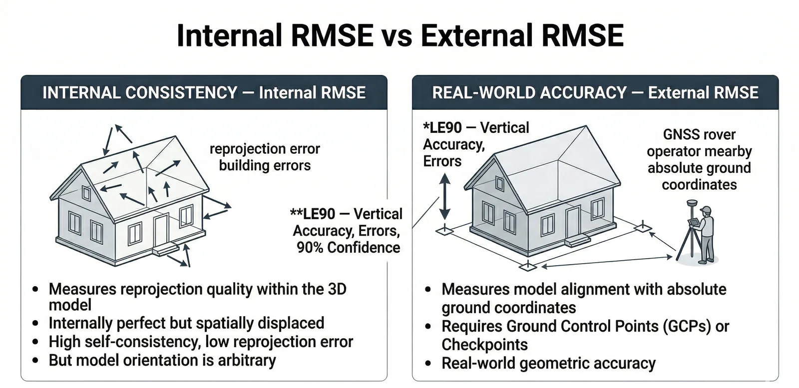
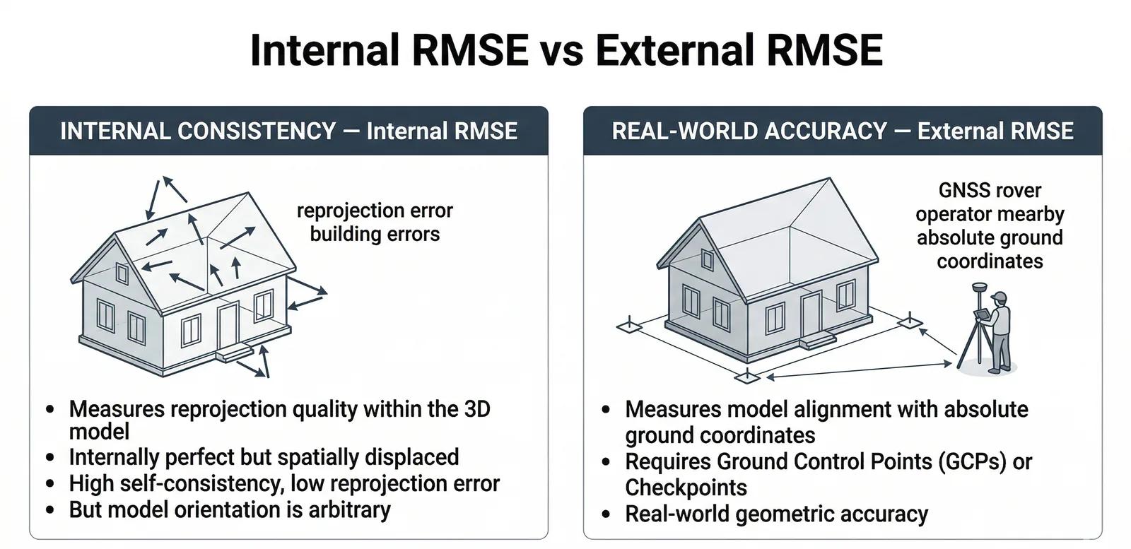
But this number tells you nothing about accuracy relative to the real world. You could have 0.2-pixel reprojection error and be positioned completely wrong geographically. The model can be internally perfect and externally divorced from reality.
Think of a scale model of a house. Windows line up, roof geometry is flawless, every detail matches at 1/100th scale. But the model is sitting 20 centimeters above where the house actually stands. Internal consistency: perfect. Position: wrong.
That’s what reprojection error tells you — how well-built the model is. Not where it sits.
The number that tells you where the model actually sits comes from checkpoints: surveyed coordinates you independently verified after the flight, at locations you never used to build the model. When software checks how closely its coordinates match those independent measurements, that’s real-world accuracy. That’s the foundation of any credible drone mapping accuracy report.
Internal versus external accuracy. That’s the distinction. Everything else flows from it. And before you worry about either, decide what accuracy you actually need — the four-tier positioning framework walks through whether your project needs full GCP workflows, RTK/PPK alone, or just consumer GPS.
RMSE: What It Actually Measures
RMSE — Root Mean Square Error — is a measure of the magnitude of your errors, in the same units as your data. It’s the square root of the mean of all squared differences between measured and true values.
Practical version: you flew a site. Your software generated coordinates for 47 checkpoints. You then surveyed those same 47 locations using survey-grade GNSS or a total station. RMSE is the square root of the average of all those squared differences.
The math is clunky by design. It penalizes big mistakes. One point that’s 50 cm off pulls the number up more than ten points that are each 5 cm off.
For drone survey work, RMSE comes in two flavors. They use the same formula. They mean completely different things.
GCP RMSE is how well the model fits the control points you fed into it. You gave the software five GCPs with survey-grade coordinates. The software used those to anchor the model, then calculated how closely its model coordinates match those same five points.
If GCP RMSE comes back as 1.2 cm, you’ve confirmed the model is locked to your ground control within 1.2 cm. You’ve also proven almost nothing about accuracy anywhere else on the site — and nothing about whether you measured those GCPs correctly to begin with.
GCP RMSE is a measure of fit, not accuracy.
Checkpoint RMSE is what matters. These are surveyed locations the software never saw. After building the model, you measured 20, 30, or ideally 40+ points on the ground. You then ask the model: what coordinates do you assign here? You compare model to surveyed. Checkpoint RMSE from that comparison is the only number that reflects real-world accuracy.
Same formula. Different meaning entirely.
A well-executed drone survey should show:
- Reprojection error: less than 1 pixel (ideally < 0.5)
- GCP RMSE: less than 2× your Ground Sample Distance
- Checkpoint RMSE: 1–2× your Ground Sample Distance
Ground Sample Distance is how many centimeters on the ground one pixel represents. Fly at 330 feet with a 24MP camera on a standard 24mm lens and you get roughly 2.5 cm GSD. Checkpoint RMSE should fall in the 2.5–5 cm range.
If checkpoint RMSE is 2 cm but reprojection error is 2 pixels, something is off. The model fits the real world but has poor internal geometry — unusual, but possible when GCPs are very accurate and imagery is mediocre.
If reprojection error is 0.3 pixels but checkpoint RMSE is 20 cm, the model is internally pristine and externally wrong. This happens routinely with nadir-only flights over variable terrain.
CE90 and LE90: Military Accuracy Standards for Drone Mapping
RMSE is the most common metric in geospatial work. CE90 and LE90 are the military and engineering cousins.
CE90 — Circular Error 90 — is a circle, centered on the true location, within which 90% of your measured positions fall. Military targeting metric originally. Engineers adopted it because it’s concrete: “90% of my measured points fall within this radius of true position.”
LE90 — Linear Error 90 — is the same concept applied vertically. The vertical distance within which 90% of your measured elevations fall.
Converting from RMSE:
- CE90 ≈ 1.5175 × RMSEr (where RMSEr = √(RMSEx² + RMSEy²), the horizontal radial RMSE)
- LE90 = 1.6449 × RMSEz
These conversions assume normally distributed errors with roughly equal X and Y components — standard for drone survey work.
Concrete example: 30 checkpoints, checkpoint RMSE of RMSEx = 3.2 cm, RMSEy = 3.8 cm, RMSEz = 6.1 cm.
CE90: √(3.2² + 3.8²) = 4.97 cm. 4.97 × 1.5175 = 7.5 cm LE90: 6.1 × 1.6449 = 10.0 cm
If a client specifies “CE90 ≤ 10 cm,” that survey meets spec with margin. But “LE90 ≤ 10 cm” just barely passes — assuming the 6.1 cm vertical RMSE holds on the next project.
ASPRS, USGS, and most photogrammetry software report RMSE. Military specs, some state DOTs, some FEMA engineering requirements, and FAA obstruction surveys use CE90/LE90. Before you accept an accuracy specification from a client, pin down which metric and which statistical framework. “Centimeter accuracy” in conversation is worth nothing.
Why Vertical Accuracy Is Always Worse
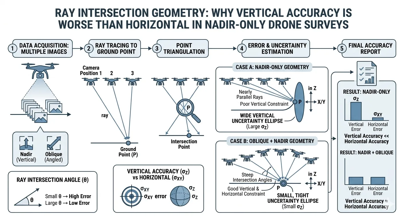
Drone photogrammetry works by ray intersection. Overlapping images, same feature identified across multiple frames, software traces where in 3D space that feature must be for it to appear at those pixel locations. The intersection gives you coordinates.
Fly nadir — straight down. You capture every image from roughly the same altitude, all pointing straight down. Rays tracing horizontal features diverge rapidly in X and Y. Good geometry. Rays tracing vertical features run nearly parallel. Terrible geometry. A small error in the camera’s estimated position produces proportionally larger Z errors.
Shallow intersection angles mean high sensitivity to position errors. That’s the tradeoff with nadir-only flights.
Vertical accuracy in nadir-only drone surveys runs 2–3 times worse than horizontal. Horizontal checkpoint RMSE of 4 cm? Expect vertical at 8–12 cm, even with solid GCPs.
The fix is oblique imagery — a second pass with the camera tilted 20–35 degrees off vertical. Now you image the same ground from multiple angles, creating strong vertical ray intersection geometry.
Štroner et al. (2021) documented nadir-only drone surveys producing vertical RMSE in the 20–40 cm range. Adding oblique passes brought vertical RMSE under 3 cm — on sites without GCPs, using direct PPK/RTK positioning only. James & Robson (2014) — the foundational paper on doming error — showed oblique imagery reduces DEM error by up to two orders of magnitude.
The cost is a few extra minutes of flight time. Oblique passes belong on every accuracy-critical survey now. The improvement is too consistent to skip.
Spotting doming in your checkpoint residuals: Doming is the most common systematic error in drone DEMs — the surface curves like a bowl or dome across the project area. The cause: near-parallel imaging directions combined with imprecise lens distortion correction. Z residuals positive at the center, negative at the edges (or vice versa) — that’s doming. Random, non-patterned residuals — that’s noise. Noise is what you want.
Other systematic error patterns:
- All Z residuals the same sign = vertical bias. Check your geoid correction. A missing geoid conversion introduces 26–174 foot vertical shifts depending on your location in the US.
- X or Y residuals consistently same sign = horizontal systematic error. Look for a datum mismatch or boresight calibration issue.
- No pattern, alternating signs = random noise. Normal.
Reading a Drone Mapping Accuracy Report Like a Professional
Processing is done. Quality report is open. Here’s what each number means.
Median of Reprojection Error (pixels): Internal consistency. Should be ≤ 1 pixel; < 0.5 is good; < 0.3 is excellent. Does not indicate real-world accuracy.
GCP RMS Error (in ground units — cm or m): How closely the model fits the control points you provided. Useful for internal QC, not for accuracy claims.
Checkpoint RMS Error (in ground units): The only number for client accuracy reports. Real-world accuracy against independent validation points.
Image Overlap Statistics: Median overlapping images per location. Minimum 3 for processing; 5 is standard minimum; 7–9 for high-accuracy work. Yellow or red zones in your overlap map mean degraded accuracy in those areas — full stop.
Camera Optimization — Focal Length Change: Optimized focal length differs from initial value by more than 5%? Flag it. Likely culprits: incorrect camera calibration, poor image geometry, or a large temperature swing during the flight.
Red flags:
- Zero checkpoints listed — accuracy claim is entirely unvalidated.
- Only 3–4 GCPs used — high risk of overfitting, no independent proof.
- GCP RMSE very low (< 0.5 cm) while reprojection error is high (> 1.5 pixels) — the software forced the model to fit GCPs at the expense of image geometry.
- All GCPs clustered in one area — rest of the site is underconstrained. A common pattern: five GCPs ending up in one corner because that’s where site access is easy. Three-quarters of the survey ends up with nothing constraining it.
- Image overlap map showing yellow or red zones — local accuracy failures in those areas.
Metashape terminology note: “Marker Accuracy” = GCP residuals (fit to control, not accuracy). “Check point accuracy” = the real accuracy number. Metashape feeds a marker designated as a GCP into bundle adjustment. A marker designated as a checkpoint stays out — validation only.
What “Centimeter Accuracy” Actually Means
DJI’s marketing says the P4 RTK achieves “1 cm RTK accuracy.”
That’s the GNSS receiver’s positioning precision under ideal conditions — good sky view, no multipath, stable atmosphere. It tells you where the camera was when the shutter fired. It says nothing about the accuracy of your deliverable.
Real-world DJI P4 RTK, no GCPs, disciplined workflow:
- Horizontal: 2–5 cm reliably achievable
- Vertical: 3–8 cm achievable; 10–30+ cm possible on nadir-only flights with doming
With proper GCP validation: horizontal often reaches 2–4 cm. Vertical depends heavily on flight geometry.
“Centimeter-level accuracy” covers 1–9.9 cm. Ninefold range. It’s marketing language, not a specification. Your checkpoint RMSE — horizontal and vertical, separately, from independent checkpoints, stated against your GCP configuration — is the professional standard.
Accuracy Classes: How to Know What You Need
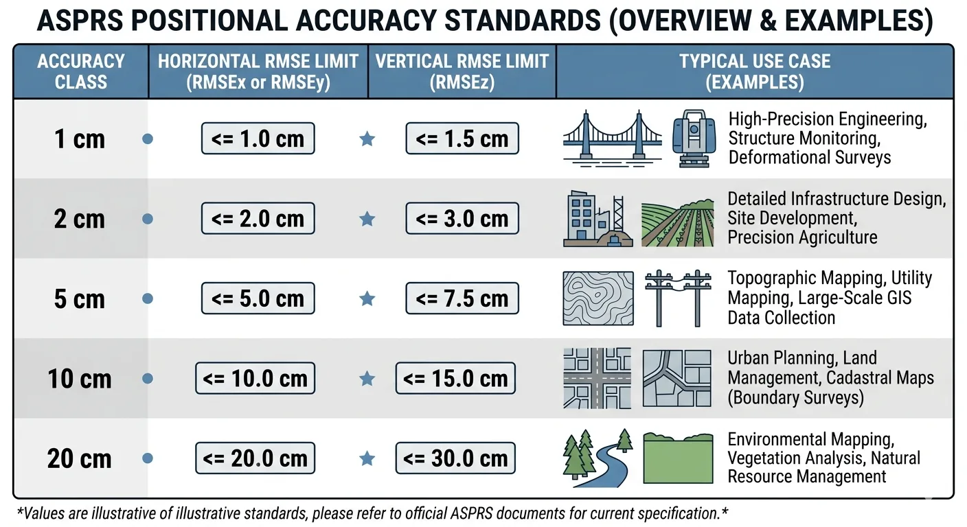
The ASPRS Positional Accuracy Standards, Edition 2 (2023–2024), sets the current North American benchmark. Accuracy classes are defined by horizontal and vertical RMSE:
| Accuracy Class | Horizontal RMSE | Vertical RMSE | Typical Use |
|---|---|---|---|
| 1 cm | ≤ 1.0 cm | ≤ 1.5 cm | High-precision engineering, machine control, structural monitoring |
| 2 cm | ≤ 2.0 cm | ≤ 3.0 cm | Large-scale engineering, precision construction |
| 5 cm | ≤ 5.0 cm | ≤ 7.5 cm | Topographic mapping 1:500 |
| 10 cm | ≤ 10.0 cm | ≤ 15.0 cm | Topographic mapping 1:1000, USGS QL2 equivalent |
| 20 cm | ≤ 20.0 cm | ≤ 30.0 cm | Topographic mapping 1:2000, USGS QL3 equivalent |
Edition 2 also raised the minimum independent checkpoint requirement from 20 to 30 for accuracy certification. If your project needs to meet a formal standard, budget for 30 checkpoints. No shortcuts.
Application examples:
- Engineering topo: 5 cm class minimum; 2 cm class for tight grades
- Construction volumes: 5 cm class; vertical is the critical axis
- FEMA floodplain mapping: 10 cm class (QL2); 30+ independent checkpoints required
- As-built surveys: 1–5 cm depending on feature type
- Precision ag: 10–30 cm typically sufficient; relative accuracy usually matters more than absolute
- Legal boundary surveys: Drones cannot perform boundary work. Regulatory line, not a technical limitation.
Bottom Line
Accuracy in drone surveys is not mysterious. It’s measurement. You measure against ground truth — surveyed checkpoints — and report the difference.
When a client asks how accurate you are, you have real language now. Not “centimeter-level.” Your actual checkpoint RMSE, horizontal and vertical, validated against independent checkpoints, compared to an ASPRS accuracy class.
That’s the professional standard. That’s what the number means.
For the full picture on GCPs — count, placement, and checkpoint validation — that’s covered here.